
System and method for recording dynamic change of laser ablated matter at nanosecond time resolution

A time resolution, laser ablation technology, applied in the direction of using optical devices, measuring devices, instruments, etc., can solve problems such as the inability to accurately record the dynamic morphology of laser ablation objects

Inactive Publication Date: 2018-02-02
CHINA UNIV OF GEOSCIENCES (WUHAN)
View PDF8 Cites 3 Cited by
  • Summary
  • Abstract
  • Description
  • Claims
  • Application Information

AI Technical Summary

Problems solved by technology

When the ablation laser pulse width is on the order of nanoseconds, picoseconds, or femtoseconds, it is impossible to accurately record the dynamic morphology of laser ablation objects at a certain moment

Method used


Image

  • System and method for recording dynamic change of laser ablated matter at nanosecond time resolution
  • System and method for recording dynamic change of laser ablated matter at nanosecond time resolution

Examples


Embodiment approach

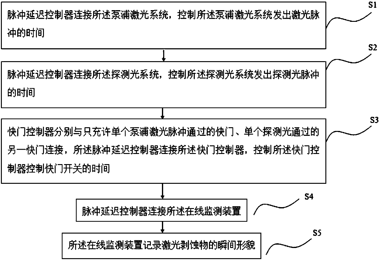
[0022] Refer to attached figure 2 , The embodiment of the present invention also provides a method for implementing a system for recording the dynamic changes of laser ablation objects with nanosecond time resolution, comprising the following steps:

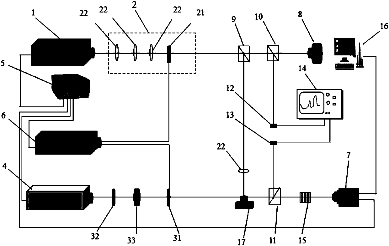
[0023] (1) The pulse delay controller 5 is connected to the pump laser system 1 to control the time when the pump laser system 1 emits laser pulses; the laser pulse emitted by the pump laser system 1 is focused on the target through the focusing optical path 2 sample surface;

[0024] (2) The pulse delay controller 5 is connected to the detection light system 4 to control the time when the detection light system 4 sends out the detection light; on the target sample;

[0025] (3) The shutter controller 6 is respectively connected with the first shutter 21 that only allows a single laser pulse to pass through, and the second shutter 31 that a single detection light passes through. The pulse delay controller 5 is connected with t...


PUM


Abstract

The invention discloses a system and a method for recording the dynamic change of a laser ablated matter at nanosecond time resolution. A pulse delay controller controls the time when a pump laser system emits laser pulse and the time when a probe light system emits probe light in order to achieve a time delay between the two kinds of pulse light. The probe light emitted by the probe light systemfalls on the surface of a target sample, and a shadow formed after the probe light is transmitted through a laser ablated matter is imaged in a camera of an online monitoring device. The camera can accurately record the instantaneous morphology of shock wave, plasma and eruptive materials. The system and the method can be used to study the dynamic change law of aerosol particles formed from laserablated particles in the air or under inert carrier gas, and can help to study the influence of the number, diameter and morphology of ablated particles on the effect of geochemical element fractionation.

Description

technical field [0001] The invention belongs to the technical field of earth micro-area analytical chemistry and micro-nano processing, and specifically relates to a system and method for recording dynamic changes of laser ablated objects with nanosecond time resolution. Background technique [0002] When the focused laser pulse energy density exceeds the target ablation threshold, irreversible ablation of the target will occur, and some target materials will be separated from the target surface in the form of atoms, molecules, ions, etc. in an instant. Although the duration of the entire denudation process is on the order of nanoseconds, microseconds or even milliseconds, it is still a dynamic process. The time response of the commonly used laser system and laser detection system is not constant but a variable, and the analysis of the dynamic morphology of the instantaneous laser ablation will help to analyze the dynamic physical and chemical mechanism of the interaction be...

Claims


Application Information

Patent Timeline
IPC IPC(8): G01B11/24
CPCG01B11/24
Inventor 吕涛胡杨李子涵孟久灵张长江
Owner CHINA UNIV OF GEOSCIENCES (WUHAN)
Learn More