Supercharge Your Innovation With Domain-Expert AI Agents!

Method for analyzing CT scanning result based on box counting method

A technology of CT scanning and analysis method, which is applied in the field of industrial CT scanning, and can solve problems such as large error in results and loss of information

Active Publication Date: 2018-02-02
HARBIN INST OF TECH
View PDF3 Cites 2 Cited by
  • Summary
  • Abstract
  • Description
  • Claims
  • Application Information

AI Technical Summary

Problems solved by technology

[0006] The purpose of the present invention is to solve the problems of information loss and large result errors in image processing in the prior art, and propose a method for analyzing CT scan results based on the box counting method

Method used


Image

  • Method for analyzing CT scanning result based on box counting method
  • Method for analyzing CT scanning result based on box counting method
  • Method for analyzing CT scanning result based on box counting method

Examples


specific Embodiment approach 1

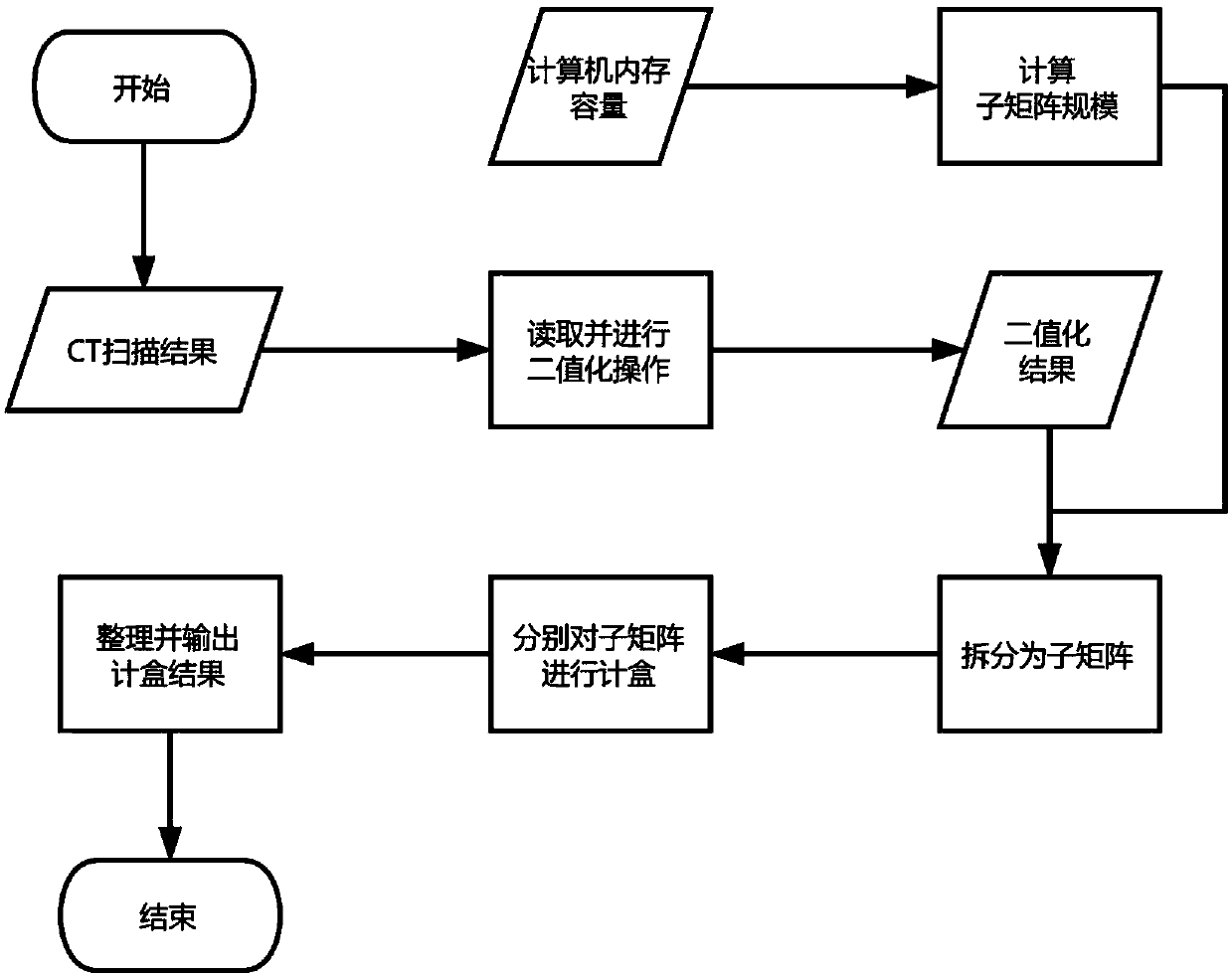
[0020] Specific implementation mode one: as figure 1 Shown, a kind of CT scan result analysis method based on counting box method comprises the following steps:

[0021] Step 1: The computer reads all CT scan pictures and performs binarization processing on all CT scan pictures, and obtains the binarization result of each picture as a two-dimensional matrix [A];

[0022] Step 2: Arrange the two-dimensional matrix [A] of all pictures obtained in step one according to the height order to obtain the three-dimensional matrix [C], and the number of layers of [C] is the number of CT scan pictures (the total number of tomograms);

[0023] Step 3: divide the three-dimensional matrix [C] that step two obtains into L three-dimensional sub-matrices according to the memory capacity of the computer itself;

[0024] Step 4: Carry out box counting to the L three-dimensional sub-matrices divided in step 3, and obtain a box counting result sequence;

[0025] Step 5: Integrate the box countin...

specific Embodiment approach 2

[0027] Specific embodiment 2: The difference between this embodiment and specific embodiment 1 is: in the step 1, the computer reads the CT scan pictures and adopts the method of parallel computing to perform binarization processing on all CT scan pictures to obtain the value of each picture The specific process of binarizing the result into a two-dimensional matrix [A] is:

[0028] The element A in row i and column j in the two-dimensional matrix [A] is calculated from the pixels in the picture ij value; if the gray value of the i-th row and j-column pixel is greater than or equal to the threshold, then A ij The value of is counted as 1, otherwise it is counted as 0. The method of parallel computing is used to calculate as many pixels as possible at the same time.

[0029] If the CPU of the computer executing the invention has multiple threads at the same time, all the threads of the computer are called to process different pixels at the same time.

[0030] Other steps and...

specific Embodiment approach 3

[0031] Embodiment 3: The difference between this embodiment and Embodiment 1 or 2 is that the threshold is 50% of the default value of the computer or artificially set (according to the brightness of the picture).

[0032] Other steps and parameters are the same as those in Embodiment 1 or Embodiment 2.


PUM


Abstract

The invention relates to a method for analyzing a CT scanning result based on a box counting method, which aims to solve problems of information loss and great result error generated in image processing in the prior art. The method comprises the steps that one, a computer reads all CT scanning pictures and performs binarization processing on all of the CT scanning pictures, and the binarization result of each picture is a two-dimensional matrix [A]; two, the two-dimensional matrixes [A], which are acquired in the step one, of all pictures are arranged according to a height sequence to obtain athree-dimensional matrix; three, the three-dimensional matrix [C] acquired in the step two is divided into L three-dimensional sub-matrixes according to the memory capacity of the computer; four, performing box counting on the L three-dimensional sub-matrixes divided in the step three to obtain box counting result sequences; and five, the box counting result sequences of the three-dimensional sub-matrixes are integrated to obtain a score dimension of the CT scanning result. The method is applied to the field of industrial CT scanning.

Description

technical field [0001] The invention relates to the field of industrial CT scanning, in particular to a method for analyzing CT scanning results based on a box counting method. Background technique [0002] Industrial CT scanning is a technology that uses X-rays or γ-rays to obtain its internal information and output it as a two-dimensional tomographic image or a three-dimensional stereoscopic image without damaging the detection object. Furthermore, the user processes the scanning results as required. Obtaining the fractal dimension of the image by the box counting method is one of the commonly used processing methods. Because this method is easy to understand and can generate a clear value that can describe the geometric properties of the detection object, it is widely used. means of preliminary analysis. [0003] With the gradual improvement of the accuracy of scanning technology, users can obtain more and more detailed information through CT technology, and the volume ...

Claims


Application Information

Patent Timeline
IPC IPC(8): G06T7/00
CPCG06T7/0004G06T2207/10081
Inventor 杨旭麻硕朱飞张孝存王凤来
Owner HARBIN INST OF TECH
Features
  • R&D
  • Intellectual Property
  • Life Sciences
  • Materials
  • Tech Scout
  • Unparalleled Data Quality
  • Higher Quality Content
  • 60% Fewer Hallucinations
Learn More