
Regulating type mining machinery gear heat treatment device

A heat treatment device and adjustable technology, applied in heat treatment furnaces, heat treatment equipment, quenching devices, etc., can solve problems such as inability to adjust, damage to gears and rotating parts, and blocking of rotating parts, so as to achieve good stability in use and reasonable structure settings , fast fix effect

Pending Publication Date: 2018-02-06
浙江西维亚进出口有限公司
View PDF0 Cites 0 Cited by
  • Summary
  • Abstract
  • Description
  • Claims
  • Application Information

AI Technical Summary

Problems solved by technology

[0002] During the processing of mining machinery, due to the harsh working environment, rotating parts are easily stuck by stones during use, causing damage to gears and rotating parts. However, the structure and volume of mining machinery are generally large. , in order to ensure the stability of the workpiece, it is necessary to heat treat the gears and rotating parts. Due to their large volume, the heat treatment equipment using traditional technology is mainly composed of a chassis and a support frame. All solid-state induction heater and water storage tank, which heat the workpiece through the all-solid-state induction heater and cool the heated workpiece through the water storage tank, but they cannot effectively fix the workpiece, and at the same time, they cannot meet the needs of the heat treatment position. Adjustment, which will greatly affect the efficiency of heat treatment for large gears, and also affect the cost of heat treatment, so the applicability and practicability are limited

Method used


Image

  • Regulating type mining machinery gear heat treatment device
  • Regulating type mining machinery gear heat treatment device

Examples


Embodiment 1

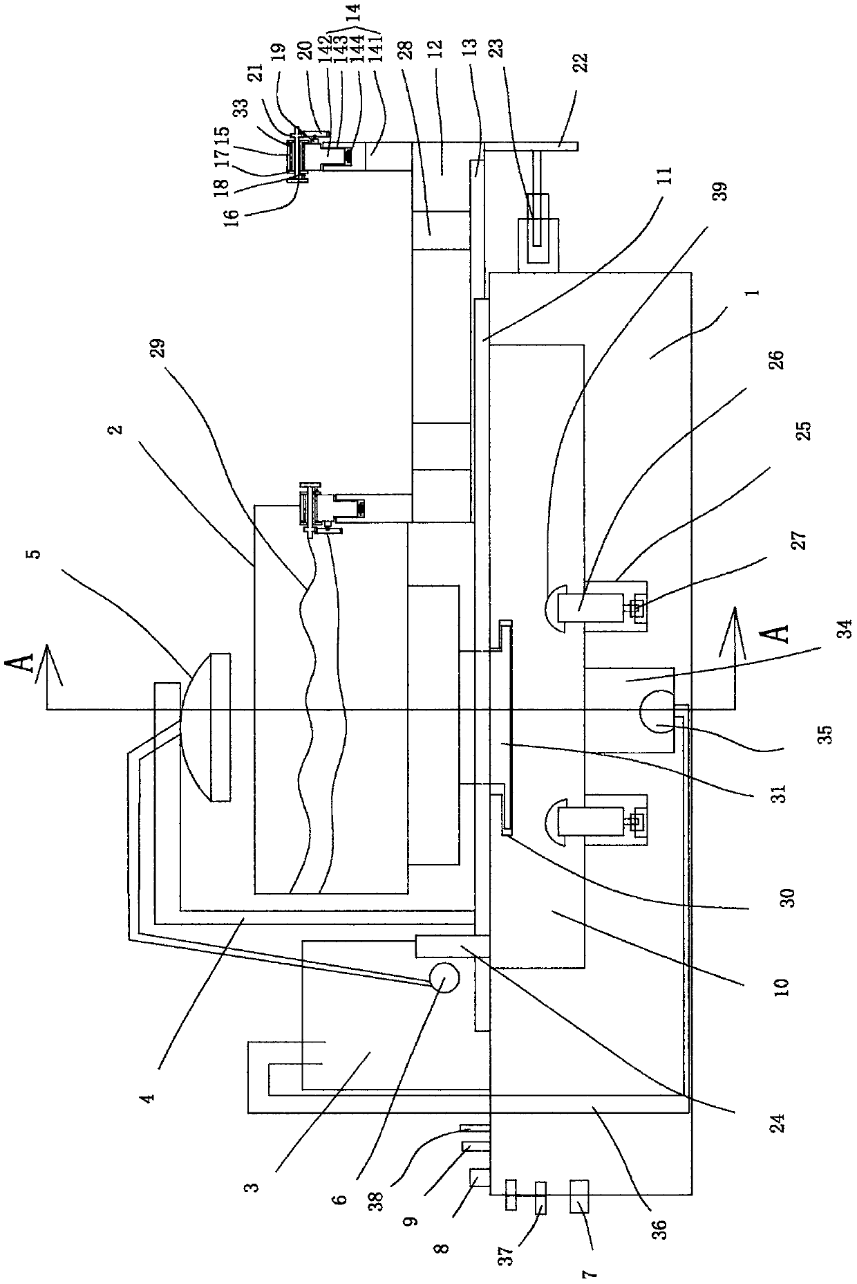
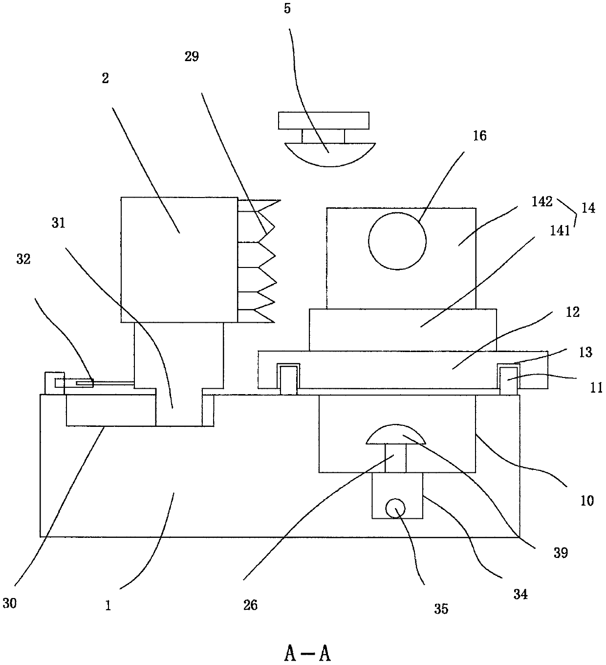
[0018] figure 1 with figure 2 A specific embodiment of the invention is shown in which figure 1 It is a structural schematic diagram of the present invention; figure 2 for figure 1 Middle A-A sectional view.

[0019] See figure 1 with figure 2 , an adjustable gear heat treatment device for mining machinery, comprising a base 1, an all-solid induction heater 2 and a water storage tank 3 arranged on the base 1, the all-solid induction heater and the water storage tank are structures of the prior art, It is also a conventional use structure in this technical field, so it is not described in detail. A cooling bracket 4 is fixed on the base 1, a shower head 5 is fixed on the cooling bracket 4, and a shower head 5 is fixed on the cooling bracket 4. A shower pipe and a shower pump 6 connecting the shower head 5 and the water storage tank 3 are fixed, and a power socket 7 and a control switch 8 connected to the solid state induction heater 2 are arranged on the base 1 and con...


PUM


Abstract

The invention discloses a regulating type mining machine gear heat treatment device which comprises a base, a full solid state sensing heater and a water storage tank, wherein the full solid state sensing heater and the water storage tank are arranged on the base, a cooling support is fixed to the base, a spray head is fixed to the cooling support, a concave cavity is formed in the base, an opening is formed in the top surface of the concave cavity, a guide rail protrusion is arranged on the top surface of the base, a gear bearing seat is further arranged on the top surface of the base, clamping frames are respectively fixed to the two ends of the gear bearing seat, round holes are horizontally formed in the clamping frames, T-shaped abutting blocks are arranged on the clamping frames, H-shaped annular seats are arranged in the round holes, rotation motors are fixed to the outer lateral sides of the clamping frames, driving gears are fixed to spindles of the rotation motors, and toothgrooves are formed in the surfaces of vertical rods of the T-shaped abutting blocks. The regulating type mining machine gear heat treatment device disclosed by the invention has reasonable structuralarrangement, not only greatly improves a heat treatment efficiency and reduces heat treatment cost, but also can effectively ensure heat treatment quality and has the advantages of good stability, strong adaptability and good practicability.

Description

technical field [0001] The invention belongs to the technical field of mining machinery processing, and in particular relates to an adjustable gear heat treatment device for mining machinery. Background technique [0002] During the processing of mining machinery, due to the harsh working environment, rotating parts are easily stuck by stones during use, causing damage to gears and rotating parts. However, the structure and volume of mining machinery are generally large. , in order to ensure the stability of the workpiece, it is necessary to heat treat the gears and rotating parts. Due to their large volume, the heat treatment equipment using traditional technology is mainly composed of a chassis and a support frame. All solid-state induction heater and water storage tank, which heat the workpiece through the all-solid-state induction heater and cool the heated workpiece through the water storage tank, but they cannot effectively fix the workpiece, and at the same time, they...

Claims


Application Information

Patent Timeline
IPC IPC(8): C21D9/32C21D1/667
CPCC21D1/667C21D9/0062C21D9/32Y02P10/25
Inventor 孔晓燕
Owner 浙江西维亚进出口有限公司
Learn More