
Steam condensation device

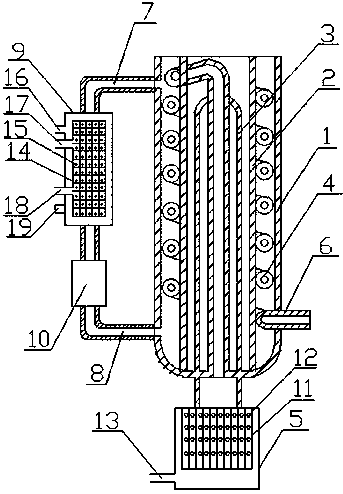
A technology of steam condensing and condensing pipes, used in steam/steam condensers, steam condensing, heating or cooling equipment, etc., can solve the problems of easily damaged gas pipes, different tap water, small cooling area, etc., to reduce potential safety hazards, Good condensation effect and water saving effect

Inactive Publication Date: 2018-02-09
QIDONG TIANSHAN TOOLS CO LTD
View PDF0 Cites 3 Cited by
  • Summary
  • Abstract
  • Description
  • Claims
  • Application Information

AI Technical Summary

Problems solved by technology

[0003] Most of the existing condensing air pipes are straight or spherical, the condensation path is short, and the cooling area is small, resulting in high temperature of the gas coming out of the outlet pipe and poor condensation effect; the existing condensing pipes are usually directly connected to the faucet, using The flow of the faucet plays the role of condensation, but the temperature of the tap water is also different in different seasons, especially in hot summer, the temperature is very high, the temperature of the tap water is also high, and the effect of condensation cannot be achieved. The tap water passes through the cooling pipe Afterwards, it is usually left directly to the sewer, resulting in a waste of water resources; when the steam in the existing condensing device enters the gas pipeline, it is not dried, and the steam contains some moisture. The moisture enters the gas pipeline for condensation, and the moisture remains in the gas pipeline. The wall and air pipe are easily damaged

Method used


Image

  • Steam condensation device

Examples


Embodiment Construction

[0015] In order to deepen the understanding of the present invention, the present invention will be further described below in conjunction with the embodiments and accompanying drawings. The embodiments are only used to explain the present invention and do not constitute a limitation to the protection scope of the present invention.

[0016] Such as figure 1 An embodiment of the steam condensing device of the present invention is shown, which includes an outer tube 1 with a hollow interior and an inner tube 2 with a hollow interior. The outer wall of the inner pipe 2 is spirally provided with a spiral condenser pipe 4, which makes the condensation path longer and the cooling area larger, so as to achieve a better condensation effect. The lower end is connected with a guide tube 5, the guide tube 5 is placed at the lower end of the outer tube 1, the lower end of the condensation tube 4 is provided with an output port 6, the output port 6 is set through the outer tube 1, and the...


PUM


Abstract

The invention relates to a steam condensing device, which comprises a hollow outer tube and a hollow inner tube, the inner tube is placed in the outer tube, the inner tube is provided with a gas delivery tube, and a spiral condensation tube is arranged around the outer wall of the inner tube for delivery. The upper end of the trachea is connected to one end of the condenser pipe, the lower end of the air delivery pipe is connected to a diversion tube, the diversion tube is placed at the lower end of the outer tube, the lower end of the condenser tube is provided with an output port, and the output port is set through the outer tube, one side of the outer tube The upper end of the water inlet pipe is connected to the water inlet pipe, and the lower end of the outer pipe side is connected to the water outlet pipe. The connection between the water inlet pipe and the water outlet pipe and the outer pipe is provided with a bell mouth. . The invention has the advantages of reasonable structure, good condensing effect, prolonging the service life of the device, safe operation, recycling of condensed water and saving water resources.

Description

Technical field: [0001] The invention relates to the field of experimental devices, in particular to a steam condensing device. Background technique: [0002] In chemical experiments, the steam condensing device is an indispensable cooling device in the distillation and reflux device. It is a laboratory equipment that promotes condensation. It usually consists of a mile-one-outer gas line tube and a condensation tube. The inner tube of the gas line tube Both ends can be connected to other experimental equipment to allow hotter gas or liquid to flow into the tube and condense. [0003] Most of the existing condensing air pipes are straight or spherical, the condensation path is short, and the cooling area is small, resulting in the high temperature of the gas coming out of the outlet pipe, and the condensation effect is poor; the existing condensing pipes are usually directly connected to the faucet. The flow of the faucet plays the role of condensation, but the temperature ...

Claims


Application Information

Patent Timeline
IPC IPC(8): B01L7/00B01D5/00B01D53/26F28B1/02
CPCB01L7/00B01D5/0012B01D5/0054B01D5/0075B01D53/26F28B1/02
Inventor 戴帅东
Owner QIDONG TIANSHAN TOOLS CO LTD
Learn More