Direct current railway steel rail flash butt welder for rapid pressure maintaining push protruding

A technology for butt welding machine and rail, applied in the field of rail welding, it can solve the problems of inconsistent three-phase current amplitude, many joint temperature drops, three-phase unbalance, etc. structure, the effect of improving reliability

Active Publication Date: 2018-02-09
METALS & CHEM RES INST CHINA ACAD OF RAILWAY SCI +3
View PDF14 Cites 5 Cited by
  • Summary
  • Abstract
  • Description
  • Claims
  • Application Information

AI Technical Summary

Problems solved by technology

The disadvantages of this welding machine are: 1) the rail centering method of this welding machine is too simple, it is impossible to set the pre-arching amount, and it is difficult to realize the alignment of the working side of the rail head side; 2) it cannot realize the rail in the static frame Pushing (deburring) is completed under the condition of clamping the rail with the moving frame, or called pressure-holding and pushing; 3) Another disadvantage is the unbalanced three-phase (three-phase current amplitude is inconsistent), because the AC welding transformer can only be Single-phase use, so the current of one phase is relatively large, and the load of the other two phases is small, and the impact on the grid power is more serious; 4) Since the upper and lower double beam structures are located above and below the symmetrical line of the rail, when the actual rail end face deviates from the center line, the Under the action of welding upsetting force, an additional bending moment in the horizontal direction will be generated. Since the structure has poor bending resistance, it is prone to horizontal bending of welded joints
However, it takes more than 15 seconds for the push-up to wait for the centering arm and the electrode to be loosened and then the push-up knife passes through the electrode to reach the push-up position. Welded joints are prone to microscopic defects

Method used


Image

  • Direct current railway steel rail flash butt welder for rapid pressure maintaining push protruding
  • Direct current railway steel rail flash butt welder for rapid pressure maintaining push protruding
  • Direct current railway steel rail flash butt welder for rapid pressure maintaining push protruding

Examples


Embodiment

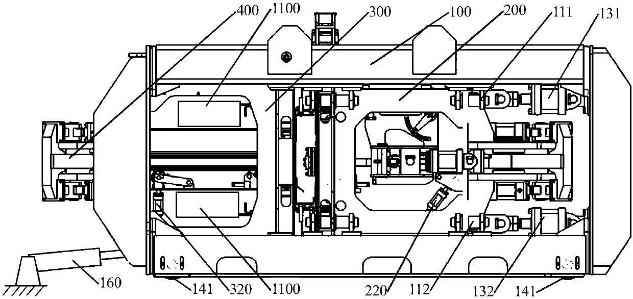
[0035] In actual work, the steel rail enters the welding machine through the side of the raceway driven frame before welding, and the parts of the rail to be welded enter the electrode side of the moving frame and the static frame respectively. At this time, in order to align the rail to be welded with the middle of the electrode, it is necessary to start the traveling oil cylinder 160 of the welding machine to drive the welder to walk longitudinally along the track on the ground until the rail to be welded is aligned with the center of the moving and static frames. Since the rail is in the middle of the upper and lower longitudinal beams of the welding machine, the horizontal and vertical bending moment components generated by the rail during welding are extremely small, which has little influence on the straightness of the joint.

[0036] Then, start the arching wheel oil cylinders 220 and 320 at the two ends of the welding machine and the rail top clamping oil cylinders 531 ...


PUM


Abstract

The invention provides a direct current railway steel rail flash butt welder for rapid pressure maintaining push protruding. The direct current railway steel rail flash butt welder comprises a frame (100), a movable frame (200), a fixed frame (300), a rail web clamping mechanism (400), a vertical electrode clamping mechanism (500), a horizontal steel rail adjusting mechanism (600) and a steel railwelding connector push protruding mechanism (700). By means of the direct current railway steel rail flash butt welder for rapid pressure maintaining push protruding, during welding upsetting, a connector is evenly stressed up and down, the bending moment caused by upsetting is eliminated, and accordingly straightness of a steel rail flash welding head is ensured. Through an independent push protruding mechanism and a special push protruding oil cylinder, push protruding in the state of vertical and horizontal connector displacement locking (connector pressure maintaining) is achieved, and the situation of connector pulling at the high temperature is avoided; and through a steel rail web connecting rod clamping mechanism, the steel rail web clamping efficiency is further improved, and meanwhile the clamping force can be adjusted by adjusting the connecting rod angle.

Description

technical field [0001] The invention relates to the field of rail welding in the railway industry, in particular to a direct-current railway rail flash butt welding machine for quickly maintaining pressure and pushing convex. Background technique [0002] At present, the steel rails used in rail transit are welded to length steel rails produced by steel mills and then laid on the line to form a seamless line. The most important method of rail welding is to use fixed rail flash welding equipment with high efficiency and stable joint quality to weld rails, so as to obtain reliable quality welded joints. [0003] Known fixed rail flash welding equipment connected by a bottom frame, see U.S. Patent US 5270514, its main feature is that the moving frame track of the welding machine is arranged at the bottom of the moving frame, and the rail to be welded is above the track, and the moving frame and The upper end of the static frame is in an open state. The structural disadvantage...

Claims


Application Information

Patent Timeline
Patent Type & Authority Applications(China)
IPC IPC(8): B23K11/04B23K11/31B23K11/36B23K37/04
CPCB23K11/002B23K11/046B23K11/31B23K11/36B23K37/0443B23K2101/26B23K2103/04Y02P70/10
Inventor 丁韦杨国涛高振坤彭鹏李力宋宏图赵国李金华胡玉堂
Owner METALS & CHEM RES INST CHINA ACAD OF RAILWAY SCI
Why Eureka
Try Eureka