Robot welding workstation for aluminum alloy heat radiator

A robot welding and radiator technology, applied in welding equipment, auxiliary welding equipment, metal processing equipment, etc., can solve the problems of low welding efficiency, troublesome positioning, troublesome welding, etc., and achieve the effect of improving welding efficiency, fast and accurate positioning

Pending Publication Date: 2018-02-09
WUXI HANSHEN ELECTRIC
0 Cites 1 Cited by

AI-Extracted Technical Summary

Problems solved by technology

[0002] The radiator includes cooling fins and ends. During the production of the radiator, it is necessary to weld between the fins and the fins and the ends. The traditional m...

Abstract

The invention relates to an aluminum alloy radiator robot welding workstation, which includes a welding robot system and a fixed turning mechanism, the fixed turning mechanism includes an active positioner and a driven positioner, and the gap between the active and driven positioners is Connect the fixed frame, the fixed frame is provided with a welding relief hole, the left and right sides of the fixed frame are provided with a sliding clamping mechanism, the sliding clamping mechanism is arranged on the guide rail, and the sliding clamping mechanism is connected to the driving cylinder, The front side of the fixed frame is provided with a fixed positioning block, and the rear side of the matched fixed frame is provided with a clamping cylinder, and the front and rear sides are also provided with a cylinder for pressing the radiator on the corner of the fixed frame. The welding robot system includes a robot The main body, welding machine, control cabinet, gas cylinder and gun cleaning station, the aluminum alloy radiator robot welding workstation can complete the welding of both sides of the radiator in one positioning, and the positioning is fast and accurate, and the welding efficiency is high.

Application Domain

Technology Topic

Image

  • Robot welding workstation for aluminum alloy heat radiator

Examples

  • Experimental program(1)

Example Embodiment

[0011] The specific embodiments of the present invention will be described below in conjunction with the drawings.
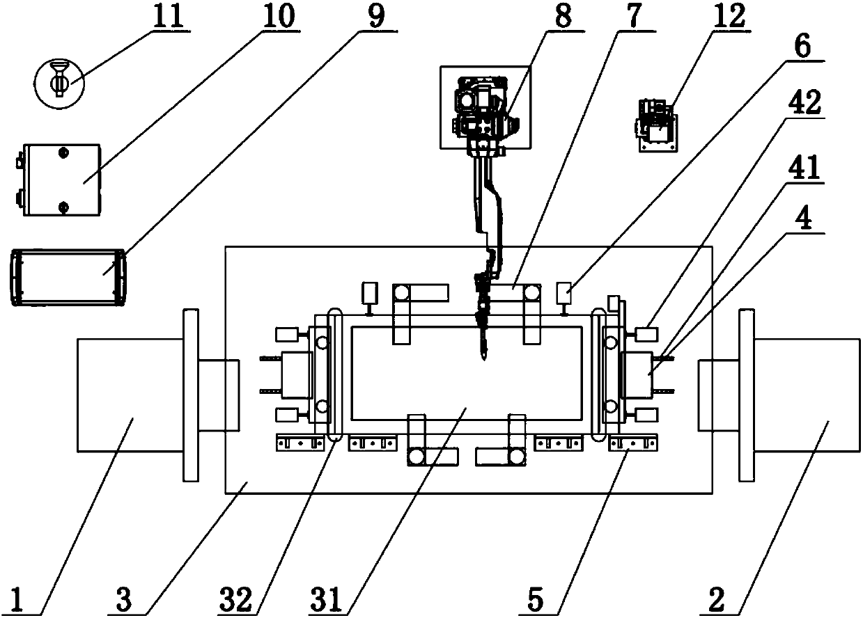
[0012] Such as figure 1 As shown, the aluminum alloy radiator robot welding workstation of this embodiment includes a welding robot system and a fixed turning mechanism. The fixed turning mechanism includes an active positioner 1 and a driven positioner 2. The active and driven positioner 1, 2 is connected to the fixed frame 3, the fixed frame 3 is provided with a rectangular relief hole 31 in the middle of the welding radiator and a waist-shaped relief hole 32 at the two ends of the welding radiator. The fixed frame 3 is provided with a sliding clamping mechanism 4 on the left and right sides. , The sliding tightening mechanism 4 is arranged on the guide rail 41, and the sliding tightening mechanism 4 is connected to the driving cylinder 42, a fixed positioning block 5 is arranged on the front side of the fixed frame 3, and a tightening cylinder 6 is arranged on the rear side of the matching fixed frame 3. A corner pressing cylinder 7 for pressing the radiator to the fixed frame 3 is also provided. The welding robot system includes a robot body 8, a welding machine 9, a control cabinet 10, a gas cylinder 11 and a gun cleaning station 12.
[0013] When the aluminum alloy radiator robot welding workstation is used, the radiator to be welded is placed on the fixed frame 3, and the sliding clamping mechanism 4 is driven by the driving cylinder 42 to slide and clamp the left and right sides of the radiator on the guide rail 41 , Fix the radiator back and forth through the clamping cylinder 6 and the fixed positioning block 5, and then press the radiator on the fixed frame 3 through the corner compression cylinder 7 to complete the radiator positioning, and then perform the radiator first through the welding robot system One side is welded. After the first side is welded, the active positioner 1 and the driven positioner 2 drive the fixed frame 3 to turn over 180°, and the welding gun of the robot body 8 passes through the rectangular relief hole 31 and the waist-shaped relief The position hole 32 is welded on the second side. After the welding is completed, the active positioner 1 and the driven positioner 2 drive the fixed frame 3 to turn over again by 180°, so that the radiator faces upwards, and then the cylinder 42 is driven and the cylinder 6 is tightened. Reset with the corner compression cylinder 7 and remove the welded radiator.
[0014] The above description is an explanation of the present invention, not a limitation of the present invention. The scope of the present invention is limited by referring to the claims. The present invention can be modified in any form without departing from the basic structure of the present invention.

PUM

no PUM

Description & Claims & Application Information

We can also present the details of the Description, Claims and Application information to help users get a comprehensive understanding of the technical details of the patent, such as background art, summary of invention, brief description of drawings, description of embodiments, and other original content. On the other hand, users can also determine the specific scope of protection of the technology through the list of claims; as well as understand the changes in the life cycle of the technology with the presentation of the patent timeline. Login to view more.

Similar technology patents

Positioning mechanism

InactiveCN104723002AOvercoming difficult positioningAccurate positioningWelding/cutting auxillary devicesAuxillary welding devicesSoftware engineeringWelding process
Owner:ANHUI JIANGHUAI AUTOMOBILE GRP CORP LTD

Novel hinge structure device

InactiveCN109277726AThe workpiece is stable and firmAccurate positioningWelding/cutting auxillary devicesAuxillary welding devicesRocker armMagnet
Owner:SHANGHAI JUNJI MACHINE EQUIP MFG CO LTD

Classification and recommendation of technical efficacy words

  • Accurate positioning
  • Improve welding efficiency

High-precision camera pan/tilt head

Owner:TIANJIN BOTAITIANYU TECH DEV CO LTD

Partial discharge collecting and positioning method, device and system

InactiveCN111175614AImprove sampling accuracyAccurate positioningPosition fixationTesting using acoustic measurementsComputational physicsPower equipment
Owner:HENAN PINGGAO ELECTRIC +2

Circuit board assembly method

InactiveCN104159414ASave assembly manpowerImprove welding efficiencyPrinted circuit assemblingReflow solderingWave soldering
Owner:SHENZHEN JIUBABA ELECTRONICS
Why Eureka
Try Eureka