
Chamfer processing method for cylindrical roller

A technology of cylindrical rollers and processing methods, which is applied to metal processing equipment, manufacturing tools, and parts of grinding machine tools. Deviation and other problems, to achieve the effect of improving dynamic unbalance, chamfering symmetry control, and improving accuracy

Inactive Publication Date: 2018-02-09
AVIC HARBIN BEARING
View PDF6 Cites 1 Cited by
  • Summary
  • Abstract
  • Description
  • Claims
  • Application Information

AI Technical Summary

Problems solved by technology

[0004] The purpose of the present invention is to solve the problems of chamfer size deviation, chamfer jump, and chamfer symmetry that cannot be effectively controlled in the existing cylindrical roller processing technology, resulting in the instability of the roller at high speed and swinging

Method used


Image

  • Chamfer processing method for cylindrical roller
  • Chamfer processing method for cylindrical roller
  • Chamfer processing method for cylindrical roller

Examples


specific Embodiment approach 1

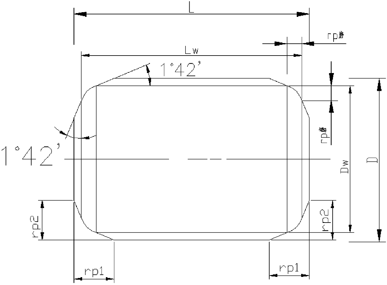
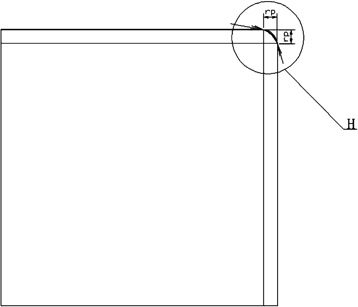
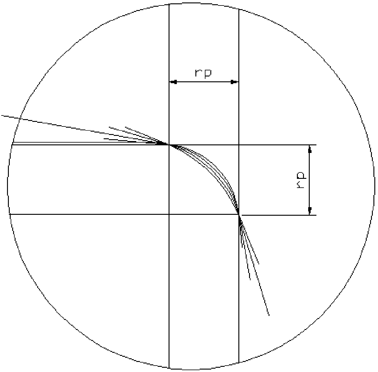
[0027] Specific implementation mode one: combine Figure 1 to Figure 5 Describe this embodiment, the chamfering processing method of a kind of cylindrical roller of this embodiment, it comprises the following processing steps:

[0028] Step 1: cut off;

[0029] Cut the bar according to the size required by the process on the CNC lathe, with an outer diameter of 0.5mm and a length of 0.5mm;

[0030] Step 2: Softly grind the outer diameter and end face of the cut bar;

[0031] Carry out soft grinding to the bar after cutting, the outer diameter removal amount of soft grinding is 0.2mm, and the end face removal amount of soft grinding is 0.18mm;

[0032] Step 3: Chamfering at both ends of the car;

[0033] On the basis of step 2, the chamfering of the cylindrical roller is carried out on the lathe, and the cutting parameters are the chamfering coordinate allowance before chamfering grinding plus the allowance of the outer diameter and the end face;

[0034] Step four: heat tr...

specific Embodiment approach 2

[0049] Specific implementation mode two: combination Figure 1 to Figure 5 To describe this embodiment, the outer contour shape of the diamond roller used in step six of this embodiment is consistent with the chamfer shape of the cylindrical roller to be ground. Such setting can make the chamfering shape reach the ideal state, ensure the consistency of the chamfering shape of the rollers in the processing process, improve the accuracy of the runout of the outer diameter of the chamfering of the rollers, and improve the dynamic unbalance of the rollers during operation. Other contents are the same as those in the first embodiment.

specific Embodiment approach 3

[0050] Specific implementation mode three: combination Figure 1 to Figure 5 To illustrate this embodiment, the processing steps after heat treatment in Step 5 of this embodiment are a rough outer diameter grinding process, an end face grinding process, a fine outer diameter grinding process, a fine end face grinding process, and a fine grinding outer diameter process. With such setting, the machining precision of the roller can meet the final precision requirement. Because the outer diameter and end surface processing of the roller need to be positioned with each other during the processing of the roller, the principle is to process the outer diameter first, and then the end surface; since the outer diameter is the main working surface, the processing accuracy is high and the busbar shape is required. Therefore, the final machining process is also outer diameter machining. Other contents are the same as those in the first or second embodiment.


PUM


Abstract

The invention discloses a chamfer processing method for a cylindrical roller, relates to improvement in cylindrical roller bearing cylindrical roller chamfer processing accuracy and aims at solving the problems of unstability in running, occurrence of abnormal wear and vibration and short service life of a roller during working caused by low accuracy and larger unbalance amount of the roller in abearing under the conditions with more complex bearing working condition, poor lubrication condition and high rotational speed. The chamfer processing method comprises a cylindrical roller chamfer grinding processing method and design of a special diamond rolling wheel for a chamfer grinder and comprises the following steps of step one, cutting; step two, soft grinding of the outer diameter and the end surface of a rod after being cut; step three, turning of chamfers at the two ends; step four, heat treatment; step five, grinding processing of the outer diameter and the end surface; step six,chamfer grinding; and step seven, outer diameter final grinding and outer diameter superfinishing. The chamfer processing method for the cylindrical roller is used for finishing the roller chamfers with high accuracy and is used for chamfer processing of the cylindrical roller.

Description

technical field [0001] The invention relates to a chamfering processing method, in particular to a chamfering processing method of a cylindrical roller. Background technique [0002] Cylindrical roller bearings operate under complex working conditions, poor lubrication conditions, and high speeds. If the roller precision is not high and the unbalance is large, the rollers will not run smoothly, and abnormal wear and vibration will occur during work. , These factors restrict the improvement of bearing service life. Part of the reason for the abnormal wear of the bearing is that the beating amount of the chamfer of the bearing roller is too large, the roller runs unstable at high speed, swings, and the abnormal contact wear with the inner ring rib. Therefore, it is necessary to improve the machining accuracy of the roller chamfer, reduce the runout of the roller chamfer to the outer diameter of the roller, and improve the processing shape of the roller chamfer. [0003] The ...

Claims


Application Information

Patent Timeline
IPC IPC(8): B24B1/00B24B53/12B24B53/14B23P15/00
CPCB24B1/00B23P15/00B24B53/12B24B53/14
Inventor 王晔王强田磊韩亭鹤刘新强姚慧英唐刚李博翰
Owner AVIC HARBIN BEARING
Learn More