Mold

A mold and fixed mold technology, applied in the field of molds for the production of various parts of different specifications, can solve the problems of not being able to produce products of various specifications, and achieve the effects of fewer processes, lower production costs, and high efficiency

Pending Publication Date: 2018-02-09
GREE ELECTRIC APPLIANCES INC
View PDF11 Cites 1 Cited by
  • Summary
  • Abstract
  • Description
  • Claims
  • Application Information

AI Technical Summary

Problems solved by technology

[0004] Therefore, the technical problem to be solved by the present invention is to overcome the d

Method used


Image

  • Mold
  • Mold
  • Mold

Examples


Embodiment 1

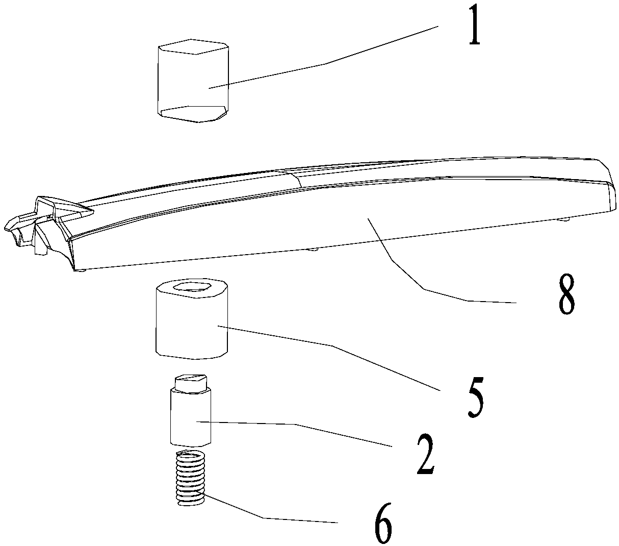
[0046] This embodiment provides a mold, such as Figures 1 to 2As shown, it includes: a fixed mold; a movable mold, a main body cavity for product 8 molding is provided between the fixed mold and the movable mold; at least one insert is installed on either the movable mold or the fixed mold piece 1, the other one is equipped with a pressing piece 2 matched with the insert, and the insert and the pressing piece 2 are detachable; in the mold closing state, the insert and the An auxiliary cavity is formed between the pressing pieces 2, and the auxiliary cavity communicates with the cavity of the main body.

[0047] In the existing technology, for products with little difference in overall structure, two sets of molds still need to be designed in the production process to produce the two products separately, which increases the difficulty of production. At the same time, for products with little demand, simultaneous development The cost of two sets of molds is higher.

[0048] I...

Embodiment 2

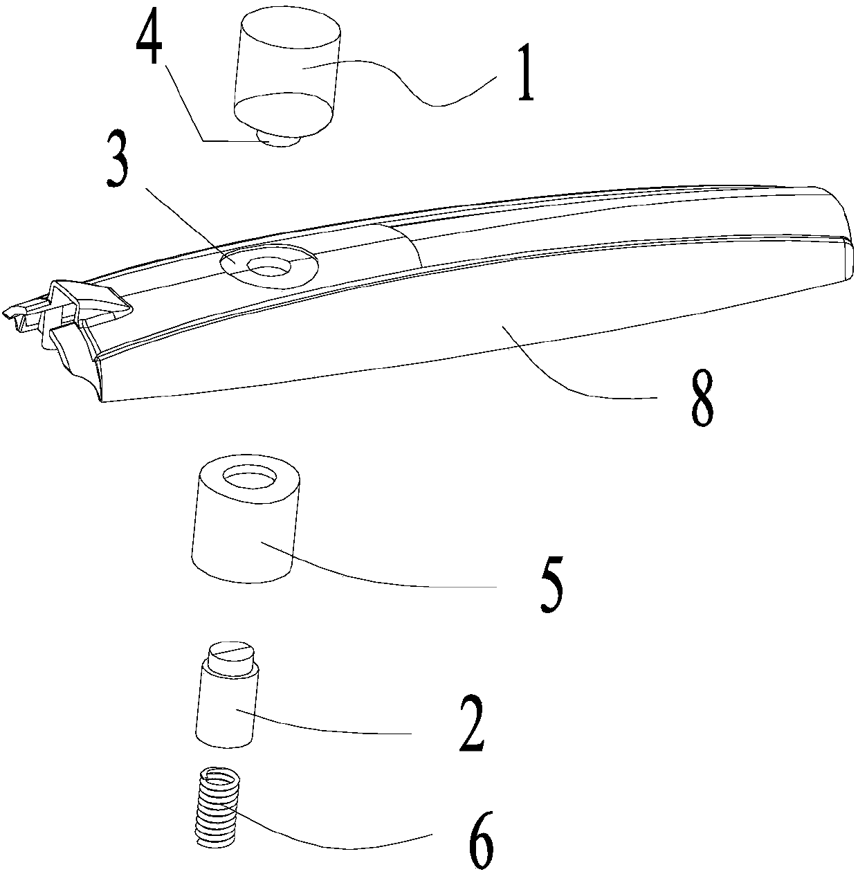
[0056] This embodiment is made on the basis of Embodiment 1. like Figure 3-5 As shown, in this embodiment, the insert 1 has a through portion 4 penetrating through the thickness of the product and abutting against the pressing piece 2 , forming a second auxiliary cavity 3 with the pressing piece 2 .

[0057] In this example, if Figure 4 As shown, the outer diameter of the through portion 4 is smaller than the outer diameter of other parts of the pressing member 2 . By setting the through part 4, the product can be better punched to form a through hole. At the same time, a step is formed at the lower end of the insert, and when the mold is closed, the insert forms a stepped counterbore on the final product.

[0058] like Figure 4 and 7 As shown, when the mold is closed, an annular chamber 9 is formed between the insert, the pressing piece 2 and the guide tube 5, and the liquid injection molding material will flow into the annular chamber 9 to form a ring. At this time, ...

Embodiment 3

[0060] This embodiment is made on the basis of Embodiment 2. In this example, if Figure 6 As shown, the part where the insert is in contact with the product is formed with reinforcing ribs. After the mold is closed, the insert forms a ring-shaped rib structure 10 on the surface of the product.

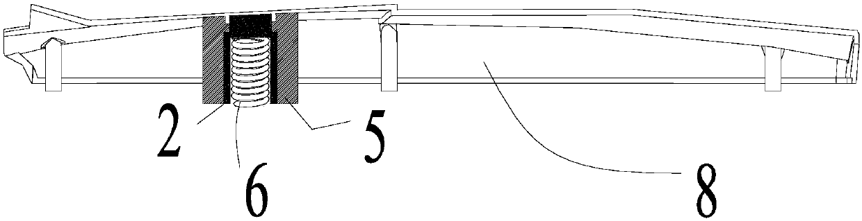
[0061] In this embodiment, the pressing member 2 is connected with a spring 6 for providing prestress toward the cavity of the main body. When the second auxiliary cavity 3 is formed between the insert and the pressing piece 2, the pressing piece 2 can be tightly attached to the insert by the spring 6, thereby ensuring the shape of the second auxiliary cavity 3 stability. Specifically, the second auxiliary cavity 3 is an annular cavity.


PUM


Abstract

The invention provides a mold. The mold comprises a fixed mold and a movable mold; a main body molding cavity for molding products is formed between the fixed mold and the movable mold; at least one insert is mounted on any one of the movable mold and the fixed mold; ejecting pieces matched with the inserts are mounted on the other one of the movable mold and the fixed mold; the inserts and the ejecting pieces are detachable; in a mold closing state, auxiliary molding cavities are formed between the inserts and the ejecting pieces; and the auxiliary molding cavities communicate with the main body molding cavity. In actual production, through change of the structures of the inserts, different auxiliary molding cavities are formed between the inserts and the ejecting pieces, and the auxiliary molding cavities form distinguishing positions between two similar products. Meanwhile, in the process of adopting different inserts, structures molded by the main body molding cavity are the same.The products with similar structures can be produced in the same set of molds only by changing the structures of the inserts, so that procedures are few, the efficiency is high, and meanwhile, the production cost is reduced.

Description

technical field [0001] The invention relates to the technical field of molds, in particular to a mold capable of producing various parts with different specifications. Background technique [0002] Injection molding is a method of producing industrial products. By injecting liquid plastic into the mold, products of different structures are formed. [0003] In the prior art, it is often necessary to produce two products with similar structures, and there is only a difference in a certain part between the two. However, although there is not much difference in the overall structure, it is still necessary to design two sets of molds in the production process to produce the two products separately. For products with small demand, the cost of developing two sets of molds at the same time is relatively high. Contents of the invention [0004] Therefore, the technical problem to be solved by the present invention is to overcome the defect that the same set of molds in the prior a...

Claims


Application Information

Patent Timeline
IPC IPC(8): B29C45/26
CPCB29C45/2673B29C2045/2677
Inventor 邱卫平王勇陈宇强王金飞瞿诗新韦成黄少杰邱建祥杨光霁
Owner GREE ELECTRIC APPLIANCES INC
Why Eureka
Try Eureka