Range hood and its fan system
A fan system and range hood technology, which is applied in the direction of oil fume removal, machines/engines, mechanical equipment, etc., can solve the problems of poor automatic cleaning effect of range hoods, and achieve the effect of improving the automatic cleaning effect
- Summary
- Abstract
- Description
- Claims
- Application Information
AI Technical Summary
Problems solved by technology
Method used
Image
Examples
no. 1 example
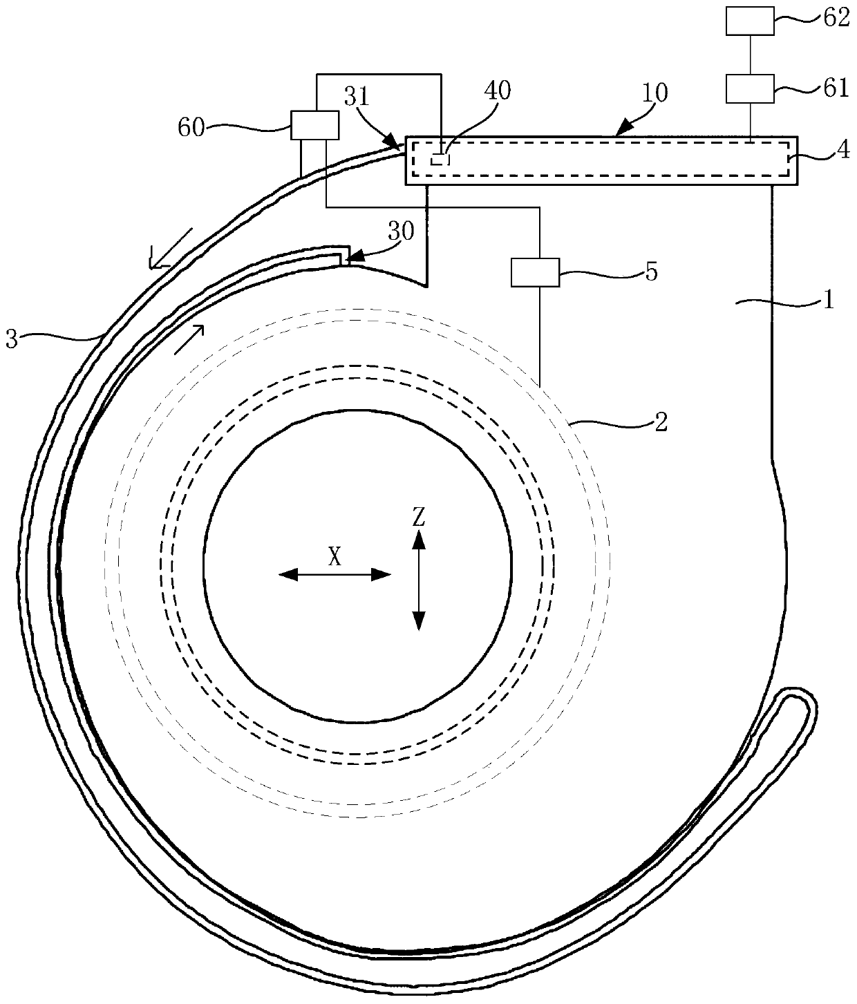
[0080] This embodiment provides a range hood, such as figure 1 As shown, the range hood includes a fan system, the fan system includes a volute 1 and an impeller 2, the impeller 2 is located in the inner cavity (not shown) of the volute 1, and when the range hood smokes the range hood, the impeller 2 rotates, A negative pressure is formed above the stove, and the fume gas in the room is sucked into the inner cavity of the volute 1 .
[0081] The blower system also includes an automatic cleaning device, which is used for cleaning oil stains on the range hood automatically rather than manually. The automatic cleaning device includes a heating pipe 3 for gas to pass through, and the heating pipe 3 can melt the oil stain on the part to be cleaned by heating at least one oily part to be cleaned on the range hood, and then flow into the oil collection of the range hood In the device, so as to achieve the function of automatic cleaning. It should be noted that, in the technical sol...
no. 2 example
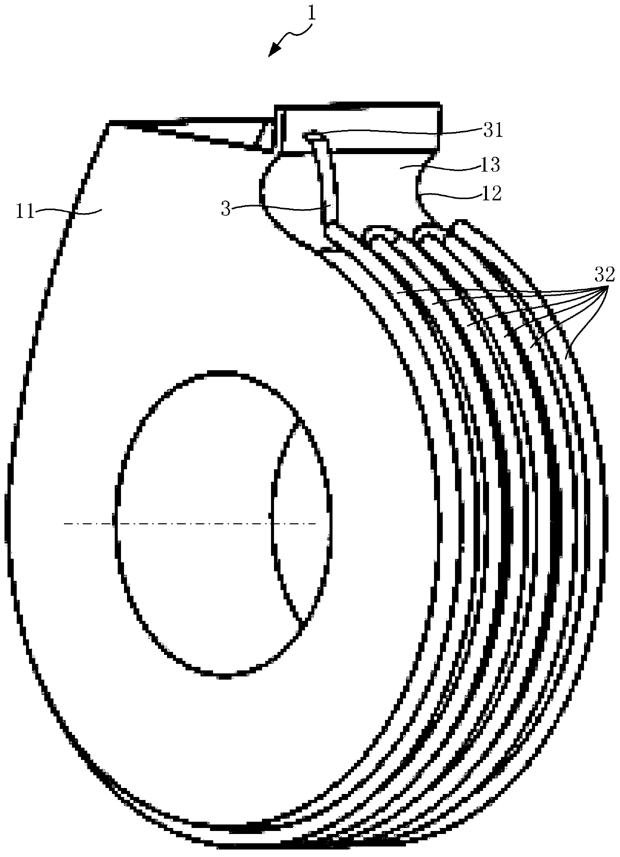
[0113] The difference between the second embodiment and the first embodiment lies in the arrangement of the heating tubes on the volute. In the second embodiment, as Figure 6 As shown, the heating pipe 3 located on the shroud 13 includes a first section of pipe 32 extending along the circumference of the volute 1, and at least two second sections of pipe 33 extending along the axial direction of the volute 1, each of the first sections The two-section tubes 33 are sequentially arranged along the circumferential direction of the volute 1, and two adjacent second-section tubes 33 are connected at one of their ends close to each other, and one end of the first-section tube 32 is connected to one of the second-section tubes. 33 are connected at one end, and the inlet 31 of the heating pipe 3 is arranged on the first section of pipe 32 . By arranging the heating pipe 3 extending in a winding manner on the outer wall of the enclosure 13, the length of the heating pipe 3 can be inc...
no. 3 example
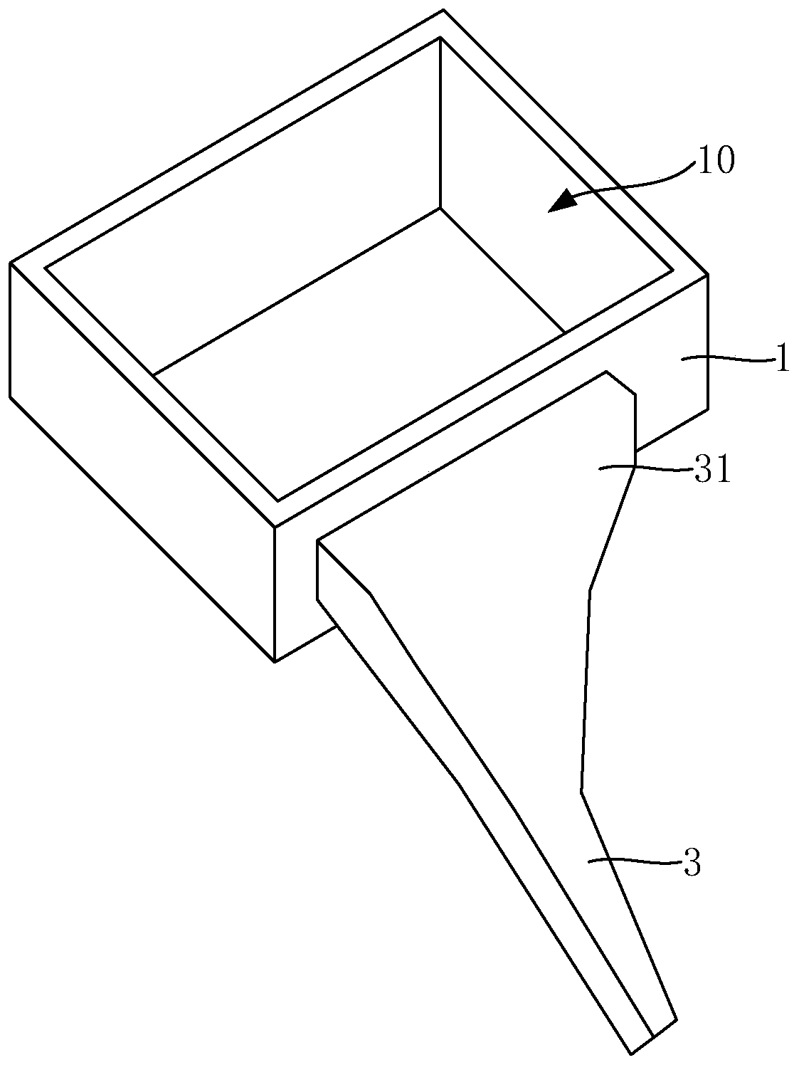
[0116] The difference between the third embodiment and the first embodiment is that in the third embodiment, if Figure 7 As shown, an opening (not shown) is provided on the surrounding plate 13 close to the air outlet 10 of the volute 1, and the opening is located on the rear side of the surrounding plate 13. The so-called rear side refers to the front and rear direction X of the range hood. on the side facing away from the user. The outlet 30 of the heating pipe 3 leads to this opening, so that the hot gas discharged from the outlet 30 can be sent into the inner cavity of the volute 1 .
PUM
 Abstract
Description
Claims
Application Information
 - R&D
- Intellectual Property
- Life Sciences
- Materials
- Tech Scout
- Unparalleled Data Quality
- Higher Quality Content
- 60% Fewer Hallucinations
Browse by: Latest US Patents, China's latest patents, Technical Efficacy Thesaurus, Application Domain, Technology Topic, Popular Technical Reports.
© 2025 PatSnap. All rights reserved.Legal|Privacy policy|Modern Slavery Act Transparency Statement|Sitemap|About US| Contact US: help@patsnap.com


