Hydraulic pressure testing system of high-pressure hydraulic pump and testing method

A technology of testing system and hydraulic pump, applied in fluid pressure actuating system testing, fluid pressure actuating system components, fluid pressure actuating devices, etc., can solve the problem of high labor intensity, low degree of automated operation, and complex hydraulic system for testers. and other problems, to achieve the effect of compact structure, high degree of automation and high control precision

Active Publication Date: 2018-02-09
BEIJING TIANMA INTELLIGENT CONTROL TECH CO LTD +1
View PDF7 Cites 4 Cited by
  • Summary
  • Abstract
  • Description
  • Claims
  • Application Information

AI Technical Summary

Problems solved by technology

The traditional test method needs to connect the unloading valve in the hydraulic system. The hydraulic system is relatively complex, and the traditional mechanical unloading valve adopts manual adjustment, which has the disadvantages of high labor intensity for testers, low test frequency, and low degree of automatic operation.

Method used


Image

  • Hydraulic pressure testing system of high-pressure hydraulic pump and testing method
  • Hydraulic pressure testing system of high-pressure hydraulic pump and testing method
  • Hydraulic pressure testing system of high-pressure hydraulic pump and testing method

Examples


Embodiment 1

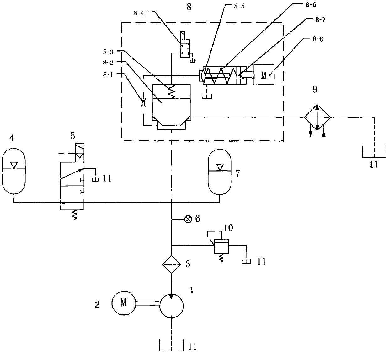
[0074] figure 1 It is the principle diagram of the hydraulic pump test system of the present invention, which mainly includes: 1-high-pressure hydraulic pump to be tested; 2-drive motor; 3-filter; 4-low pressure accumulator; 5-pilot type electromagnetic reversing valve; 6-pressure sensor; 7-high pressure accumulator; 8-digital pressure regulating valve; 9-cooler; 10-safety valve; 11-liquid tank.

[0075] The driving motor 2 drives the tested high-pressure hydraulic pump 1 to absorb liquid from the liquid tank 11, and the oil returns to the liquid tank after passing through the filter 3 digital pressure regulating valve 8 and the cooler 9; at the outlet of the tested high-pressure hydraulic pump 1 A high-pressure accumulator 7 and a low-pressure accumulator 4 are connected in parallel, and a pilot-operated electromagnetic reversing valve 5 is connected in series before the low-pressure accumulator 4; at the same time, a pressure filter 3 and a sensor are connected to the outlet...

Embodiment 2

[0083] see Figure 4 , the other connections of the hydraulic system are the same as in Embodiment 1. In this embodiment, the electromagnetic reversing valve uses a pilot-operated double-spool electromagnetic reversing valve 12, wherein the inlet of the first spool 12-1 is connected to the tested high-pressure hydraulic pump. 1 is connected to the outlet, the outlet is connected to the low-pressure accumulator 4 and the inlet of the second spool 12-2, and the outlet of the second spool 12-2 is connected to the liquid tank 11. Wherein the first spool is responsible for on-off, and the second spool makes the liquid in the low-pressure accumulator return to the liquid tank.

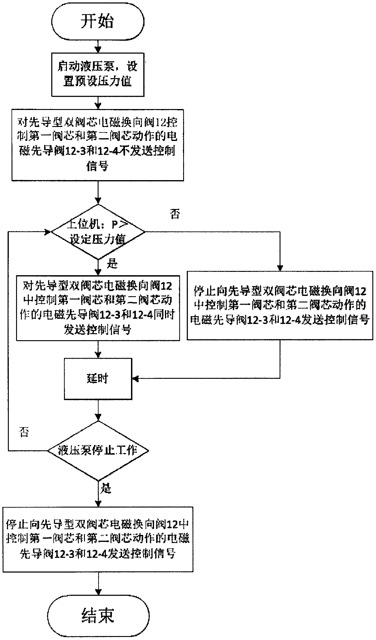
[0084] The voltage stabilization scheme of its hydraulic pump test system is realized by the following voltage stabilization scheme. Combined with the host computer software, its control process is as follows: Figure 5 Shown:

[0085] First, the high-pressure hydraulic pump 1 to be tested is started, and ...

Embodiment 2

[0089] The advantage of adopting the double spool structure in the second embodiment is that if the electromagnetic pilot valve controlling the action of the first spool fails, when the system pressure is greater than the set pressure, the control part will control the action of the first spool and the second spool. The electromagnetic pilot valve sends control signals at the same time. At this time, the first spool does not act due to the failure of the electromagnetic pilot valve that controls the action of the first spool. When the high-pressure oil from the hydraulic pump returns to the liquid tank through this channel, the low-pressure accumulator is protected; if the electromagnetic pilot valve that controls the action of the second spool fails, when the system pressure is greater than the set pressure, the control part sends The electromagnetic pilot valve that controls the actions of the first spool and the second spool sends a control signal at the same time, and the f...


PUM


Abstract

The invention discloses a hydraulic pressure testing system of a high-pressure hydraulic pump and a testing method. The hydraulic pressure testing system comprises a tested high-pressure hydraulic pump, a digital pressure adjusting valve, a liquid box, a high-pressure energy storer, a low-pressure energy storer, an energy storer switching device, a pressure sensor and a control part. An outlet oilway of the high-pressure hydraulic pump is connected with the high-pressure energy storer in parallel; the low-pressure energy storer communicates with an outlet oil way of the tested high-pressure hydraulic pump through the energy storer switching device; and oil drained by the tested high-pressure pump is returned to the liquid box after passing through the digital pressure adjusting valve. Thedigital pressure adjusting valve achieves an effect of adjusting the outlet pressure of the tested high-pressure hydraulic pump so as to verify performances of the tested high-pressure hydraulic pumpunder different pressure conditions.

Description

technical field [0001] The invention relates to a hydraulic pump testing hydraulic system and a testing method, in particular to a high-pressure hydraulic pump testing hydraulic system and a using method. Background technique [0002] With the continuous improvement of the technical level, the nominal pressure of the hydraulic pump is constantly developing towards high pressure, which puts forward higher requirements for the hydraulic system used for high-pressure hydraulic pump testing. [0003] On the one hand, at present, high-pressure hydraulic pumps generally adopt a plunger structure, so pressure and flow pulsation often occur in the hydraulic system, and the pulsation can be reduced by connecting an accumulator at the outlet of the hydraulic pump. However, in the performance test of the high-pressure hydraulic pump, Due to the high nominal pressure of the high-pressure hydraulic pump, and the impact test of the hydraulic pump when leaving the factory, this leads to a ...

Claims


Application Information

Patent Timeline
Patent Type & Authority Applications(China)
IPC IPC(8): F15B19/00F15B1/02F15B21/04
CPCF15B1/02F15B19/005F15B21/041
Inventor 韦文术刘文超李俊士牛剑峰周如林王伟王松刘杰杨立吴桐
Owner BEIJING TIANMA INTELLIGENT CONTROL TECH CO LTD
Why Eureka
Try Eureka