Worm gear type cam contour profile detector

A worm gear and detector technology, applied in instruments, measuring devices, optical devices, etc., can solve the problems of low efficiency, error, large workload, etc.

Inactive Publication Date: 2018-02-09
GUILIN UNIV OF ELECTRONIC TECH
View PDF0 Cites 2 Cited by
  • Summary
  • Abstract
  • Description
  • Claims
  • Application Information

AI Technical Summary

Problems solved by technology

This measurement method has low efficiency, heavy workload, long test time, and the staff is prone to fatigue and large errors may occur
In the latter measurement method, the measurement process and data processing are carried out automatically, and the measurement efficiency is high, which not only ensures the measurement accuracy but also reduces the fatigue strength, but has higher requirements on the rotation accuracy of the cam and the clamping accuracy of the related fixtures.

Method used


Image

  • Worm gear type cam contour profile detector
  • Worm gear type cam contour profile detector

Examples


Embodiment

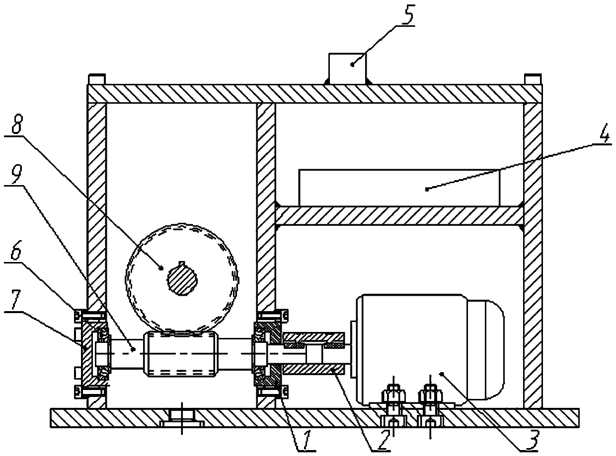
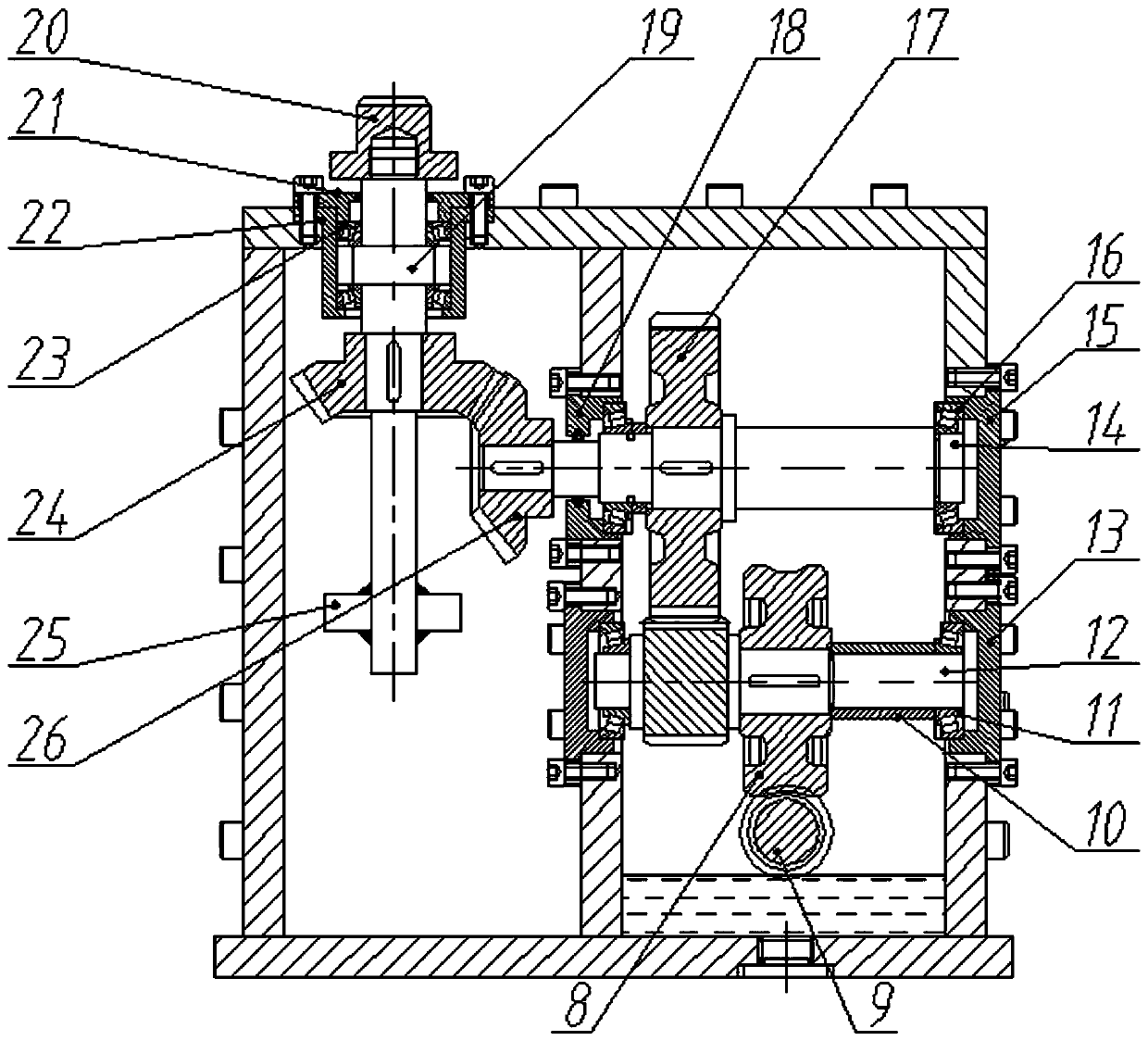
[0026] see figure 1 figure 2 , a worm gear cam profile detector, including a box, also includes a transmission unit and a control unit,

[0027] The transmission unit includes a worm wheel 8, a worm 9, a first bearing 6, a second bearing 11, a third bearing 16, a first transmission shaft 14, a second transmission shaft 19, a gear shaft 12, a first spur gear 17-1, The second spur gear 17-2, the clamp 20, the fourth bearing 23, the first bevel gear 24 and the second bevel gear 26;

[0028] The worm 9 is fixed on the bottom of the box, and the two ends of the worm 9 are arranged on the box through the first bearing 6;

[0029] The two ends of the gear shaft 12 are arranged on the casing through the second bearing 11, and the worm wheel 8 is arranged on the gear shaft 12 to mesh with the worm screw 9;

[0030] The first transmission shaft 14 is arranged on the box body through the third bearing 16, and the spur gear 17 and the second bevel gear 26 are coaxially fitted on the f...


PUM


Abstract

The invention discloses a worm gear type cam profile detector, which includes a box body, a transmission unit and a control unit, and the transmission unit includes a worm wheel, a worm, a first bearing, a second bearing, a third bearing, a first The transmission shaft, the second transmission shaft, the gear shaft, the spur gear, the fixture, the fourth bearing, the first bevel gear and the second bevel gear; the control unit includes a distance sensor, a circular grating and a control module. The rotation of the transmission unit drives the rotation of the measured cam on the fixture, and the rotation information of the measured cam is collected to the control module through the distance sensor and the circular grating. This profile detector is small in size, low in cost, fast in detection speed, high in measurement accuracy and good in practicability, and can meet the needs of on-line detection in production lines.

Description

technical field [0001] The invention relates to the technical field of cam profile measuring instruments, in particular to a worm gear type cam profile measuring instrument. Background technique [0002] The cam and the measurement parameters of the cam mainly include: lift, multiple cam mutual space position angles, radial runout, speed and acceleration and other related parameters. The cam lift and the spatial position angle are the main parameters of the two measurement parameters. The measurement methods mainly include manual measurement with optical instruments and measurement with a special cam automatic measuring instrument. The former method uses the optical dividing head to divide, and the Abbe measuring head is used to measure the lift, and the measurement results are calculated by the measuring personnel. This measurement method has low efficiency, heavy workload, and long test time, and the staff is prone to fatigue and large errors may occur. In the latter mea...

Claims


Application Information

Patent Timeline
IPC IPC(8): G01B11/24
CPCG01B11/24
Inventor 杨雪康周峰林瑞匡兵
Owner GUILIN UNIV OF ELECTRONIC TECH
Why Eureka
Try Eureka