
Valve rod chamfer machining device

A processing device and valve stem technology, which is applied in the direction of grinding drive devices, metal processing equipment, grinding/polishing safety devices, etc., can solve problems such as shaking, lower production efficiency, and inconvenient loading of valve stem rough materials

Pending Publication Date: 2018-02-13
浙江千亚自动化设备有限公司
View PDF0 Cites 3 Cited by
  • Summary
  • Abstract
  • Description
  • Claims
  • Application Information

AI Technical Summary

Problems solved by technology

[0002] In the production and processing of the valve stem, it is necessary to perform multiple processing on the formed rough material, including the processing of the chamfering of the end face of the rough material of the valve stem. The rough material of the valve stem can basically see the general shape of the valve stem, that is, it has a thick For the head and the slender stem, since the valve stem to be processed is made of coarse material, although the overall size deviation is not large, there is still a certain deviation, which makes it difficult to chamfer the end face of the stem and ensure accurate positioning. As a result, shaking occurs during processing, which leads to deviations in processing and affects the yield rate. After the rough material of the valve stem to be processed is discharged from the vibrating plate, it is usually positioned through a larger head, that is, the head is stuck on the track. On the other hand, the stem passes through the track and droops downward, which is very inconvenient for the end of the stem to be chamfered. It is also difficult to adapt to automatic processing without using a vibrating plate, and it is also very difficult for the valve stem to discharge coarse material. Inconvenient, the same is very inconvenient to load the rough material of the valve stem, which reduces production efficiency. At the same time, the collection of materials after processing is also very inconvenient. It is difficult to fully automate the operations of loading, clamping, processing and receiving blanks.

Method used


Image

  • Valve rod chamfer machining device
  • Valve rod chamfer machining device
  • Valve rod chamfer machining device

Examples


Embodiment Construction

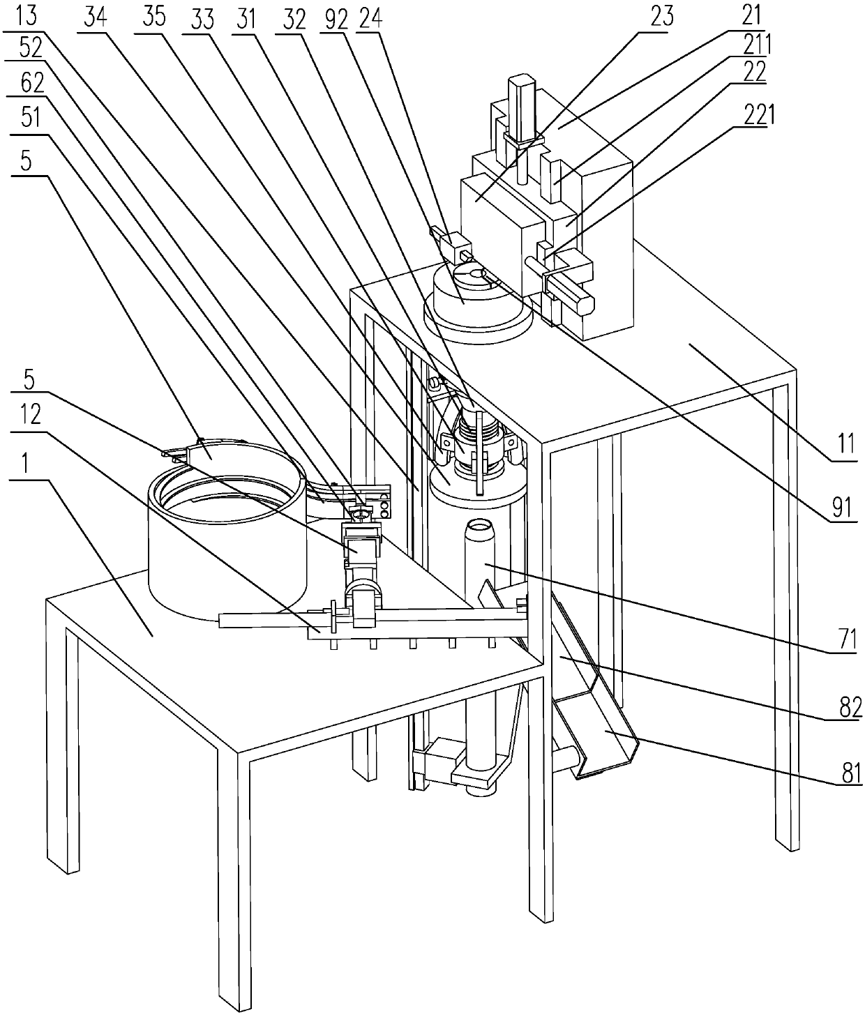
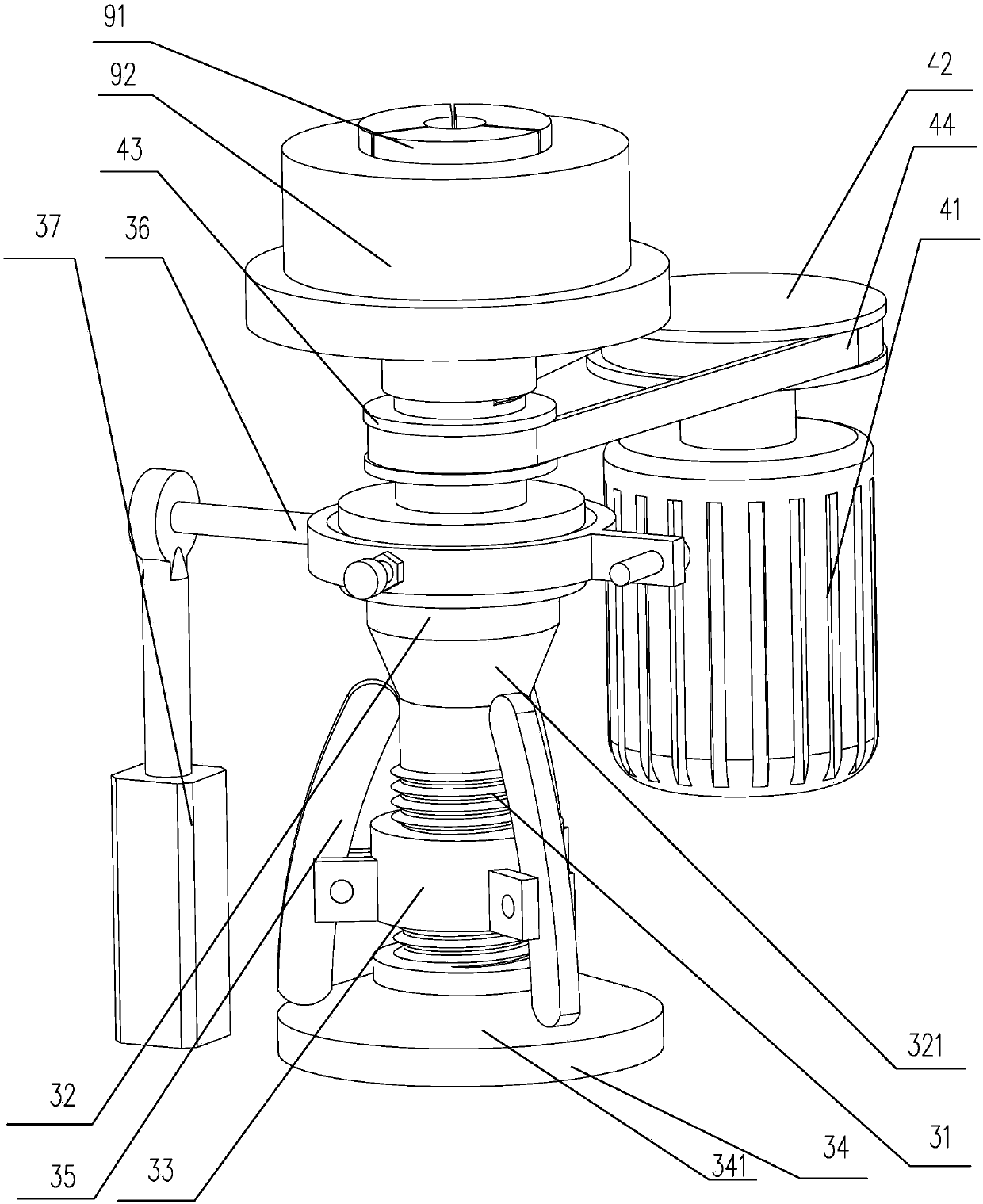
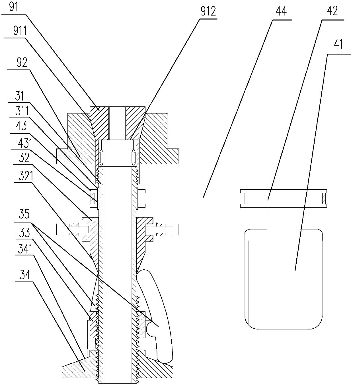
[0031] Depend on Figure 1 to Figure 7 It can be seen that the present invention discloses a valve stem chamfering processing device, which includes a bracket 1 and a vibrating plate 5 for arranging the head of the rough material of the valve stem upward and downward. The vibrating plate 5 is arranged on the bracket 1, the vibrating plate 5 includes a discharge track 51, and the discharge track 51 is provided with a discharge port 52 on the side wall, and the discharge track 51 is provided with a valve stem at the corresponding position of the discharge port 52. The draw-in groove 511 that the material head falls into, the draw-in groove 511 is connected with the discharge port 52, and the support 1 is provided with a processing platform 11, a feeding mechanism, a fastening mechanism, a grinding mechanism and a material receiving mechanism. A processing hole 14 is provided on the processing platform 11, and a grinding mechanism is provided on the processing platform 11, and th...


PUM


Abstract

The invention discloses a valve rod chamfer machining device which comprises a support and a vibrating disc. The vibrating disc is arranged on the support. A discharging outlet is formed in the vibrating disc. A feeding mechanism, a fastening mechanism, a grinding mechanism and a collecting mechanism are arranged on the support. The fastening mechanism comprises a fixing tube. The grinding mechanism comprises a cutter used for grinding a valve rod coarse material. The fixing tube is arranged on the support in a sliding mode in the vertical direction. The upper end of the fixing tube is arranged in a position corresponding to the cutter, and the lower end of the fixing tube is a free end. The feeding mechanism comprises a conveying column used for feeding the valve rod coarse material intothe fixing tube, and a conveying arm used for feeding the material to the conveying column. The conveying column is arranged below the fixing tube. The conveying arm is arranged between the fixing tube and the discharging outlet in a sliding mode. The collecting mechanism comprises a collecting hopper, and a first drive component used for driving the collecting hopper to stretch to the lower end of the fixing tube. The valve rod chamfer machining device is simple in structure, materials can be conveyed, fed, transferred and clamped automatically, chamfers are subjected to grinding machining, finally, the materials are collected, and the production efficiency is improved.

Description

technical field [0001] The invention belongs to the technical field of valve stem processing, in particular to a device for processing the chamfering of the valve stem. Background technique [0002] In the production and processing of the valve stem, it is necessary to perform multiple processing on the formed rough material, including the processing of the chamfering of the end face of the rough material of the valve stem. The rough material of the valve stem can basically see the general shape of the valve stem, that is, it has a thick For the head and the slender stem, since the valve stem to be processed is made of coarse material, although the overall size deviation is not large, there is still a certain deviation, which makes it difficult to chamfer the end face of the stem and ensure accurate positioning. As a result, shaking occurs during processing, which leads to deviations in processing and affects the yield rate. After the rough material of the valve stem to be p...

Claims


Application Information

Patent Timeline
IPC IPC(8): B24B9/00B24B41/00B24B41/06B24B41/02B24B47/08B24B55/00
CPCB24B9/00B24B41/005B24B41/02B24B41/06B24B47/08B24B55/00
Inventor 夏杰炜朱蔓茹夏莎莎王相如张桂银杨正坤
Owner 浙江千亚自动化设备有限公司
Learn More