
Speed reducer for conveying of pile irradiation sample

A technology of sample transmission and reducer, which is applied in the field of reducer for stacking sample transmission, which can solve the problems of radioactive pollution, sample leakage, fragmentation, etc., and achieve the effect of good stability and safety, slight vibration and noise, and compact structure

Active Publication Date: 2018-02-13
INST OF NUCLEAR PHYSICS & CHEM CHINA ACADEMY OF
View PDF5 Cites 2 Cited by
  • Summary
  • Abstract
  • Description
  • Claims
  • Application Information

AI Technical Summary

Problems solved by technology

[0004] In order to overcome the impact deformation (even broken) of the sample box in the prior art in the high-speed transmission in the pipeline and the impact deformation (or even rupture) of the bottom of the pipeline at the sample receiving place such as the irradiation tube, the receiver, the measuring tube, etc., resulting in sample leakage Affecting the measurement results and causing radioactive contamination, as well as deficiencies in the risk of equipment damage, the present invention provides a speed reducer for stacking sample transport

Method used


Image

  • Speed reducer for conveying of pile irradiation sample
  • Speed reducer for conveying of pile irradiation sample

Examples


Embodiment 1

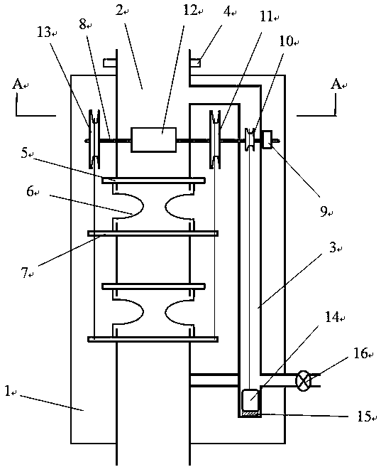
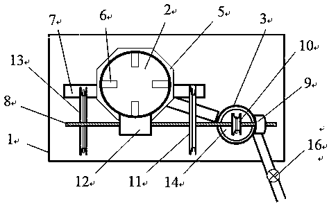
[0021] figure 1 It is a schematic diagram of the overall structure of a speed reducer for stacking sample transmission of the present invention, figure 2 for figure 1 A-A section view in. in Figure 1~Figure 2 In the present invention, a speed reducer for stacking sample transmission includes a sealed box 1, a reduction tube 2, an exhaust tube 3, a transmission mechanism, and an array of spring mechanisms. The connection relationship is: the reduction tube 2, The exhaust pipe 3, the transmission mechanism, and the spring mechanism are arranged in the sealed box 1. The reduction tube 2 and the exhaust tube 3 are arranged vertically. The two ends of the reduction tube 2 and the lower end of the exhaust tube 3 pass through the sealed box 1 and respectively connect with The sealed box 1 is airtightly connected, and the upper end of the exhaust pipe 3 is connected to the upper part of the reduction tube 2; the spring mechanism is arranged on the reduction tube 2, and the transmissio...

Embodiment 2

[0029] The structure of this embodiment is the same as that of embodiment 1, except that a set of spring mechanisms is provided on the speed reducer 2.

Embodiment 3

[0031] The structure of this embodiment is the same as that of the first embodiment. The difference is that three sets of spring mechanisms arranged up and down are arranged on the speed reducer 2, and the sliders in the three sets of spring mechanisms are fixedly connected in sequence by a wire rope.


PUM


Abstract

The invention discloses a speed reducer for conveying of a pile irradiation sample. The speed reducer comprises a sealing chamber, a speed reducing pipe, an exhaust pipe, a transmission mechanism anda plurality of spring mechanisms. The speed reducing pipe, the exhaust pipe, the transmission mechanism and the spring mechanisms are arranged in the sealing chamber; the speed reducing pipe and the exhaust pipe are arranged vertically; the two ends of the speed reducing pipe and the lower end of the exhaust pipe penetrate out of the sealing chamber and airtightly and fixedly connected with the sealing chamber; the upper end of the exhaust pipe is communicated with the upper part of the speed reducing pipe; the spring mechanisms are arranged on the speed reducing pipe; the transmission mechanism is arranged on the speed reducing pipe and the exhaust pipe; and a plurality of strip-type openings are vertically formed in the speed reducing pipe. The speed reducer for the conveying of the pileirradiation sample, as one of important and critical components of a neutron activation sample conveying system, can effectively reduce the speed of a quickly moving sample box, has the characteristics of compact structure and good sample box speed reducing effect, has a protective effect on the safety of the sample box and a conveying device and operates safely and reliably.

Description

Technical field [0001] The invention belongs to the technical fields of reactor neutron activation sample transmission technology and radioisotope preparation technology, and in particular relates to a speed reducer used for stacking sample transmission. Background technique [0002] The thermal neutron activation of the reactor and the qualitative and quantitative analysis of the designated nuclides in the sample with nuclear analysis instruments such as gamma spectrometer are a more efficient and sensitive analytical method for the determination of trace elements in the sample, which is commonly called neutron activation analysis. According to the irradiation conditions and measurement requirements of the sample, you can choose to use offline and online sample irradiation and related processing operations, that is, when the sample needs to be irradiated for a long time and the nuclides in the sample have a medium-to-long half-life, the offline mode is generally used Processing ...

Claims


Application Information

Patent Timeline
IPC IPC(8): G01N23/222G01N23/22
CPCG01N23/2204G01N23/222
Inventor 刘国平徐存礼陈静陈琪萍胡睿李兴亮魏洪源牟婉君刘业兵王定林
Owner INST OF NUCLEAR PHYSICS & CHEM CHINA ACADEMY OF
Learn More