Millimeter-wave fin-line switching feed circuit

A feeding circuit and millimeter wave technology, applied in the millimeter wave field, can solve problems such as microwave signal leakage and impact indicators, and achieve the effect of simple design and excellent circuit performance

Active Publication Date: 2018-02-13
CNGC INST NO 206 OF CHINA ARMS IND GRP
View PDF1 Cites 2 Cited by
  • Summary
  • Abstract
  • Description
  • Claims
  • Application Information

AI Technical Summary

Problems solved by technology

It takes a long time of simulation in the early stage to determine its size, and the jagged branches will also generate unwanted resonance frequencies in the waveguide cavity, which will seriously affect its indicators
Second, an insulating material needs to be pla...

Method used


Image

  • Millimeter-wave fin-line switching feed circuit
  • Millimeter-wave fin-line switching feed circuit
  • Millimeter-wave fin-line switching feed circuit

Examples


Embodiment Construction

[0017] Now in conjunction with embodiment, accompanying drawing, the present invention will be further described:

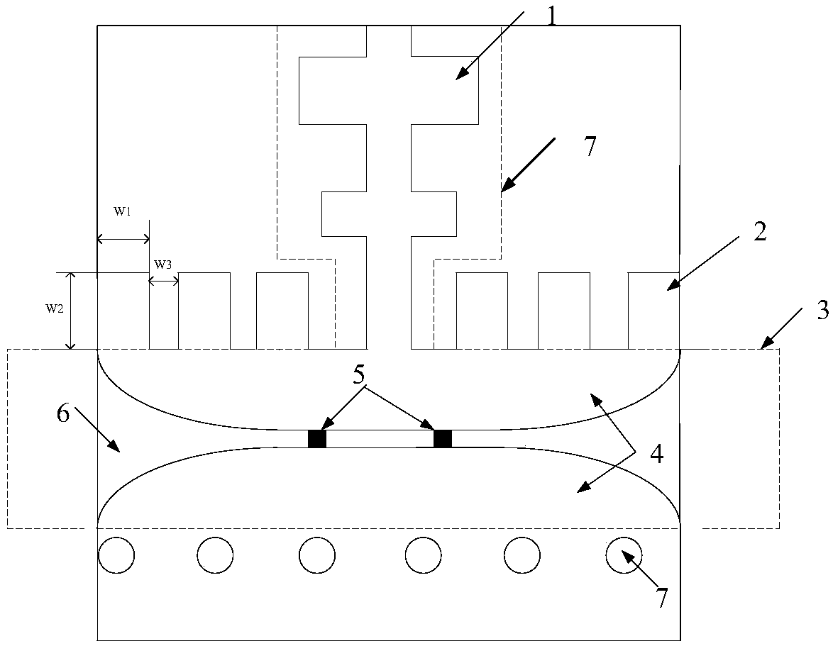
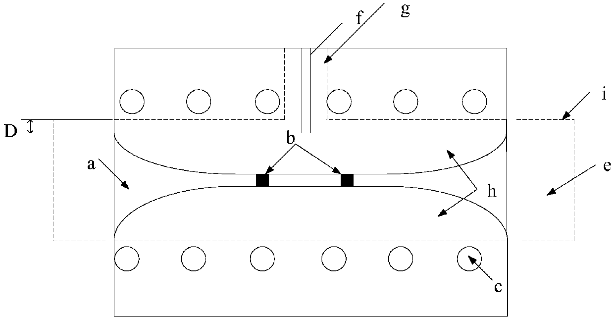
[0018] figure 1 The traditional millimeter-wave fin-line switch feeding scheme is shown. The printed circuit board substrate circuit 4 is placed between the upper and lower half waveguides, and the waveguide is divided into two. Among them, 1 is a low-pass filter, and 2 is a sawtooth branch. 3 is a waveguide cavity, 4 is a fin circuit made of copper foil, 5 is a PIN diode, 6 is a printed board substrate, 7 and a circle with the same radius as 7 are metal vias. The traditional millimeter-wave fin-line switch feeding scheme is a mature scheme, and its structure and principle will not be repeated. The main invention points of the present invention are also different from the traditional scheme: first, replace the jagged branches with Uniformly metallized vias, such as figure 2 As shown in c. The via hole placement principle is the same as that of the non-feeder ...


PUM


Abstract

The invention relates to a millimeter-wave fin-line switching feed circuit. Compared with the prior art, serrated branchknots are replaced with uniform metallized through holes; through adjustment, acertain space is reserved between a fin-line transition circuit and a waveguide wall for the optimization of insertion loss and return loss; the design is simple, and the circuit performance is excellent. From simulation results, the leakage of signals in a feed port is lower than -40 dB.

Description

technical field [0001] The invention belongs to the technical field of millimeter waves, and in particular relates to the fast and high-performance design of a millimeter wave switch feed circuit. Background technique [0002] The common design method of the millimeter-wave switch feed circuit is to use a sawtooth stub at the feed end. The design of the sawtooth stub is based on the improvement of the traditional fin line structure. This structure is used to suppress the TEM mode generated by the edge of the fin line, and also It has a good suppression of the leakage of the millimeter-wave signal (the substrate should be placed above the branch to prevent it from contacting the upper cavity and short-circuiting). It is mentioned in "Switch" that other domestic and foreign documents either do not describe the design of the feed circuit, or adopt this scheme. This solution has obvious flaws. First, the sizes W1, W2 and spacing W3 of the jagged stubs are very sensitive to sig...

Claims


Application Information

Patent Timeline
IPC IPC(8): H01P1/10
CPCH01P1/10
Inventor 赵宇博范力思荀民李建玲常进
Owner CNGC INST NO 206 OF CHINA ARMS IND GRP
Why Eureka
Try Eureka