
An easy-to-lay cable tray

A cable bridge and cable technology, applied in the direction of electrical components, etc., can solve the problems of easy damage to the outer protective layer of the cable, affecting the service life of the cable, hidden safety hazards, etc., and achieve the effects of reducing traction, prolonging service life and reducing damage

Active Publication Date: 2020-02-07
江苏鼎荣电气集团有限公司
View PDF6 Cites 0 Cited by
  • Summary
  • Abstract
  • Description
  • Claims
  • Application Information

AI Technical Summary

Problems solved by technology

[0003] Because some cables are thick and heavy, it is necessary to provide a large traction force to pull the cable into the bridge when laying the cable, and in the process of pulling, due to the high friction, it is easy to damage the outer surface of the cable. Protective layer, which affects the service life of the cable, and also poses a safety hazard

Method used


Image

  • An easy-to-lay cable tray

Examples


Embodiment Construction

[0021] In order to make the content of the present invention more clearly understood, the present invention will be further described in detail below based on the specific embodiments and in conjunction with the accompanying drawings.

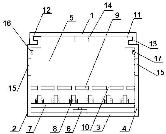
[0022] The cable tray provided by this embodiment is convenient for laying, including a cover plate 1 and an integrally formed left side plate 2, a bottom plate 3 and a right side plate 4. The cover plate 1 is set opposite to the bottom plate 3, and the cover plate 1 and the left side plate 2. The bottom plate 3 and the right side plate 4 form a cable cavity 5, wherein the upper ends of the left side plate 2 and the right side plate 4 are provided with a "匚" docking part 11, and the "匚" docking part 11 on the left side board 2 The opening of the "匚" docking part 11 on the right side plate 4 faces to the right, and the two ends of the cover plate 1 are respectively provided with left fitting parts that match the docking parts 11 of the left side ...


PUM


Abstract

The invention discloses an easy-laying cable bridge which comprises a cover plate and a left side plate, a bottom plate and a right side plate which are integrally formed. The cover plate, the left side plate, the bottom plate and the right side plate form a cable cavity, a hydraulic cylinder is arranged on the bottom plate, the output end of the hydraulic cylinder faces the cover plate, the output end of the hydraulic cylinder is fixedly connected with a lifting plate, the lifting plate is parallel to the bottom plate, at least two sets of pulley blocks are arranged on the end face of the lifting plate and away from the bottom plate, the pulley blocks are backward and forward equidistantly arranged along the guiding direction of the cable cavity, rotation planes of pulleys are parallel tothe left side plate and the right side plate, a bearing plate is arranged above the lifting plate and is parallel to the bottom plate, and through holes are formed in positions, of the bearing plate,relative to the pulleys. By the arrangement, traction force needed for cable laying can be reduced, friction force produced during cable moving can be lowered, and damage to the outer surface of a cable is reduced.

Description

technical field [0001] The invention relates to the technical field of electric installation, in particular to a cable tray which is convenient for laying. Background technique [0002] Cable tray is a cable laying device that can standardize, systematize, and generalize the laying of wires, cables, and pipe cables. Its basic types include the following: trough cable tray, a fully enclosed cable tray, which is most suitable for Laying of computer cables, communication cables, thermocouple cables and other highly sensitive system control cables has good shielding interference and cable protection in heavy corrosion environments; the tray type cable tray has light weight, large load, and shape It has the advantages of beautiful appearance, simple structure, and convenient installation. It is suitable for the installation of power cables and the laying of control cables; the stepped cable tray is suitable for laying cables with large diameters, especially for high and low power...

Claims


Application Information

Patent Timeline
Patent Type & Authority Patents(China)
IPC IPC(8): H02G3/04
CPCH02G3/0406H02G3/0412
Inventor 黄荣年
Owner 江苏鼎荣电气集团有限公司
Learn More