An e1 signal acquisition device

A signal acquisition and equipment technology, applied in the field of communication network, can solve the problems of E1 signal slip code, processing module error code, packet loss, etc., to achieve the effect of no error code and packet loss

Active Publication Date: 2018-07-17
广州市天正通信有限公司
View PDF4 Cites 0 Cited by
  • Summary
  • Abstract
  • Description
  • Claims
  • Application Information

AI Technical Summary

Problems solved by technology

At present, the E1 signal acquisition equipment used in the GSM-R network interface detection project adopts the bus mode, which requires the clock synchronization of all connected E1 signals. However, in the actual communication network, it is difficult for each output device to output clock-synchronized E1 signals.
And if the clock is not synchronized, the E1 signal will slip code, resulting in error code and packet loss in the processing module connected to the E1 signal output

Method used


Image

  • An e1 signal acquisition device
  • An e1 signal acquisition device
  • An e1 signal acquisition device

Examples


Embodiment 1

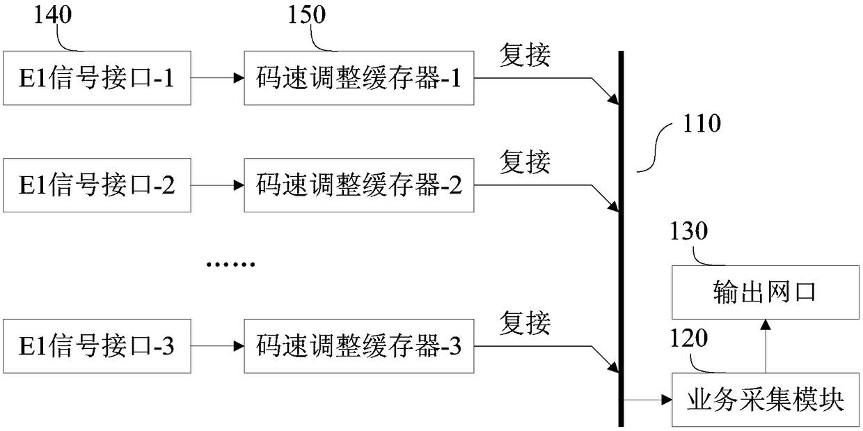
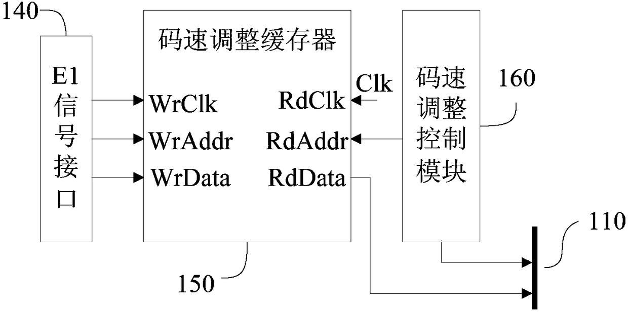
[0022] figure 1 It is a schematic structural diagram of an E1 signal acquisition device provided by Embodiment 1 of the present invention. figure 2 It is a principle diagram of code rate adjustment in Embodiment 1 of the present invention. see figure 1 with figure 2 , the E1 signal collection device includes a bus 110 , a service collection module 120 and an output network port 130 , and also includes at least one E1 signal interface 140 and a corresponding code rate adjustment buffer 150 and a code rate adjustment control module 160 .

[0023] Wherein, the E1 signal interface is used to receive the E1 signal and send the byte data corresponding to the E1 signal to the corresponding code speed adjustment buffer; specifically, the E1 signal interface connects the write clock port, the write address port and the code speed adjustment buffer of the code speed adjustment buffer Write data port, write the clock frequency, address information and byte data of E1 signal into the...

Embodiment 2

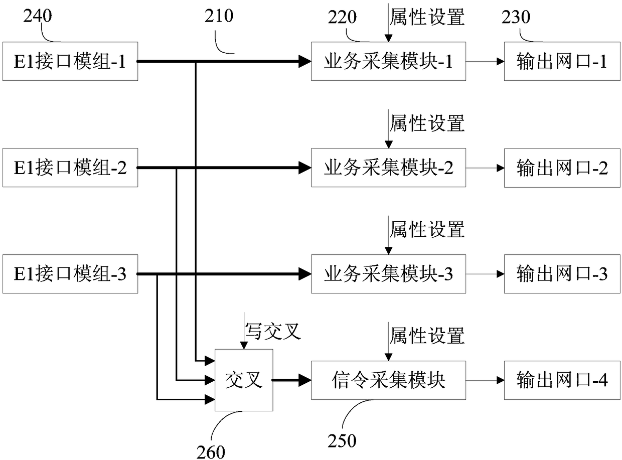
[0033] image 3 A schematic structural diagram of an E1 signal acquisition device provided in Embodiment 2 of the present invention. Such as image 3 As shown, the E1 signal acquisition device provided in this embodiment has multiple buses 210 , multiple service acquisition modules 220 and corresponding output network ports 230 .

[0034] Among them, multiple E1 signal interfaces are integrated in one E1 interface module 240, and the signals of multiple E1 signal interfaces are processed into corresponding byte data by the code rate adjustment buffer and the code rate adjustment control module, and then multiplexed to a bus 210 superior. The specific code rate adjustment principle is the same as that in Embodiment 1, and will not be repeated here.

[0035] This embodiment provides three E1 interface modules externally, which can complete the matching of many channels of E1 signals. In addition to completing the interface matching of the connected E1 signal, the interface m...


PUM


Abstract

The invention discloses E1 signal acquiring equipment. The E1 signal acquiring equipment comprises a bus, a service acquiring module, an output Ethernet port, at least one E1 signal interface, a corresponding code rate adjusting cache and a code rate adjusting control module, wherein the E1 signal interface is used for receiving an E1 signal and transmitting byte data corresponding to the E1 signal to the corresponding code rate adjusting cache; the code rate adjusting control module is used for outputting a control signal according to the cache region residual capacity of the code rate adjusting cache; the code rate adjusting cache is used for caching the byte data transmitted by the E1 signal interface, and adjusting the clock frequency of the byte data according to a preset clock signal, and outputting the byte data to the bus according to the control signal output by the code rate adjusting control module; and the service acquiring module is used for receiving and processing the byte data, and outputting the data to the output Ethernet port. Through adoption of the E1 signal acquiring equipment, clock non-synchronization of an accessed E1 signal is permitted, and the phenomenaof error code and packet loss are avoided.

Description

technical field [0001] The embodiment of the present invention relates to the field of communication networks, and in particular to an E1 signal acquisition device. Background technique [0002] In the prior art, an E1 signal collection device suitable for GSM-R networks is used to collect E1 signals and output them in different service types. At present, the E1 signal acquisition equipment used in the GSM-R network interface detection project adopts the bus mode and requires the clock synchronization of all connected E1 signals. However, in the actual communication network, it is difficult for each output device to output clock-synchronized E1 signals. However, if the clocks are not synchronized, the E1 signal will slip codes, resulting in code errors and packet loss failures in the processing module connected to the E1 signal output. Contents of the invention [0003] The present invention provides an E1 signal acquisition device to realize that the clock of the E1 sign...

Claims


Application Information

Patent Timeline
Patent Type & Authority Patents(China)
IPC IPC(8): H04L12/26
CPCH04L43/00H04L43/50
Inventor 刘华
Owner 广州市天正通信有限公司
Why Eureka
Try Eureka