A method and device for correcting communication error codes of motor encoders

A motor coding and encoder technology, applied in the field of motor encoders, can solve problems such as affecting the control process, unable to respond to changing requirements, and data error code problems, so as to ensure real-time effectiveness, avoid out-of-control problems, and meet high-precision Effect

Active Publication Date: 2019-06-28
CSR ZHUZHOU ELECTRIC LOCOMOTIVE RES INST
View PDF4 Cites 0 Cited by
  • Summary
  • Abstract
  • Description
  • Claims
  • Application Information

AI Technical Summary

Problems solved by technology

Since the encoder (sending end) and the electronic receiving device (receiving end) use various interfaces for communication, it is inevitable that there will be data errors in the decoding of the position data at the receiving end due to the disturbance of the communication line. If the position cannot be corrected in time The bit error rate problem at the data receiving end will affect the subsequent control process
[0004] In the prior art, there is already a method of correcting data aimed at improving the mechanical structure, measurement accuracy, and encoding method of the encoder. This method mainly solves the bit error problem by performing error correction at the original data sending end of the encoder. , but obviously the above method has little effect on the data error problem caused by the disturbance of the line in the communication process
There is also a method of using the built-in control algorithm of the electronic receiving device (such as a DSP processor) at the receiving end to correct and compensate the position deviation of the encoder, but this correction method mainly uses a pre-built-in algorithm, which cannot respond to different working conditions in reality. Changing requirements, and because the built-in algorithms are generally more complex, it is difficult to meet the high real-time requirements of motor control

Method used


Image

  • A method and device for correcting communication error codes of motor encoders
  • A method and device for correcting communication error codes of motor encoders
  • A method and device for correcting communication error codes of motor encoders

Examples


Embodiment Construction

[0030] The embodiments of the present invention will be described in detail below with reference to the accompanying drawings and examples, so as to fully understand and implement the implementation process of how the present invention applies technical means to solve technical problems and achieve corresponding technical effects. The embodiments of the present application and the various features in the embodiments can be combined with each other under the premise of no conflict, and the formed technical solutions all fall within the protection scope of the present invention.

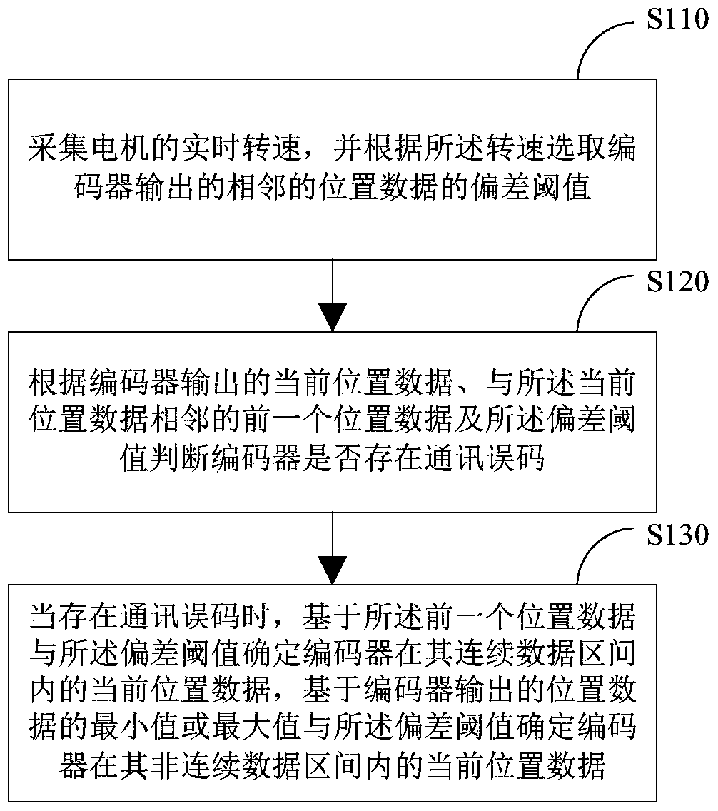
[0031] figure 1 It is a schematic flowchart of a method for correcting communication errors of a motor encoder according to an embodiment of the present invention. As shown in the figure, the method includes:

[0032] Step S110: Collect the real-time rotational speed of the motor, and select a deviation threshold of adjacent position data output by the encoder according to the collected rotational spee...


PUM


Abstract

The invention discloses a method and device for correcting the communication error codes of a motor encoder. The method includes the following steps that: the real-time rotation speed of a motor is collected, and the deviation threshold value of adjacent position data output by the encoder is selected according to the rotation speed; whether communication error codes exist on the encoder is judged according to current position data output by the encoder, last position data adjacent to the current position data, and the deviation threshold value; and when the communication error codes exist on the encoder, the current position data of the encoder in the continuous data interval of the encoder are determined according to the last position data and the deviation threshold value, and the current position data of the encoder in the discontinuous data interval of the encoder are determined according to the minimum value or maximum value of the position data outputted by the encoder and the deviation threshold value. With the method adopted, the problem of the error codes of communication data due to the possible disturbance of external environment in practical application can be solved, and the real-time validity of the position signals of the encoder can be ensured.

Description

technical field [0001] The invention belongs to the field of motor encoders, and in particular relates to a method and a device for correcting communication errors of a motor encoder. Background technique [0002] Position encoder is a sensor device used to detect motor position signal, which is widely used in motor positioning control. The position encoder can relieve the computing task of the electronic receiving device, thus eliminating the complex and expensive input device and reducing the cost of the system. [0003] The position sensor is generally connected to the electronic receiving device through a communication interface. The types of communication interfaces mainly include synchronous serial serial SSI interface, parallel interface, CANopen interface, Profibus interface, EtherNet interface and so on. Since various interfaces are used for communication between the encoder (transmitting end) and the electronic receiving device (receiving end), it is inevitable t...

Claims


Application Information

Patent Timeline
Patent Type & Authority Patents(China)
IPC IPC(8): H02P23/14
CPCH02P23/14
Inventor 尚敬梅文庆郭赞武彬刘浩平戴计生周蓉邱岳烽黄佳德
Owner CSR ZHUZHOU ELECTRIC LOCOMOTIVE RES INST
Why Eureka
Try Eureka