
Method for correcting guide current error code in image transmission

A technology of a diversion loop and an error correction method, which is applied in the field of error correction coding and decoding in image transmission, can solve problems such as the transmission error code of the diversion loop, and achieves the problem of solving the error code problem, the system hardware requirements are not high, and the practical value is high. Effect

Inactive Publication Date: 2008-04-30
SHANGHAI INST OF TECHNICAL PHYSICS - CHINESE ACAD OF SCI
View PDF0 Cites 0 Cited by
  • Summary
  • Abstract
  • Description
  • Claims
  • Application Information

AI Technical Summary

Problems solved by technology

[0004] The purpose of the present invention is to provide a coding and decoding technology in image transmission to solve the problem of bit errors in the transmission of the diversion ring

Method used


Image

  • Method for correcting guide current error code in image transmission

Examples


Embodiment Construction

[0016] The application process of this method will be further described in detail below in conjunction with an application example.

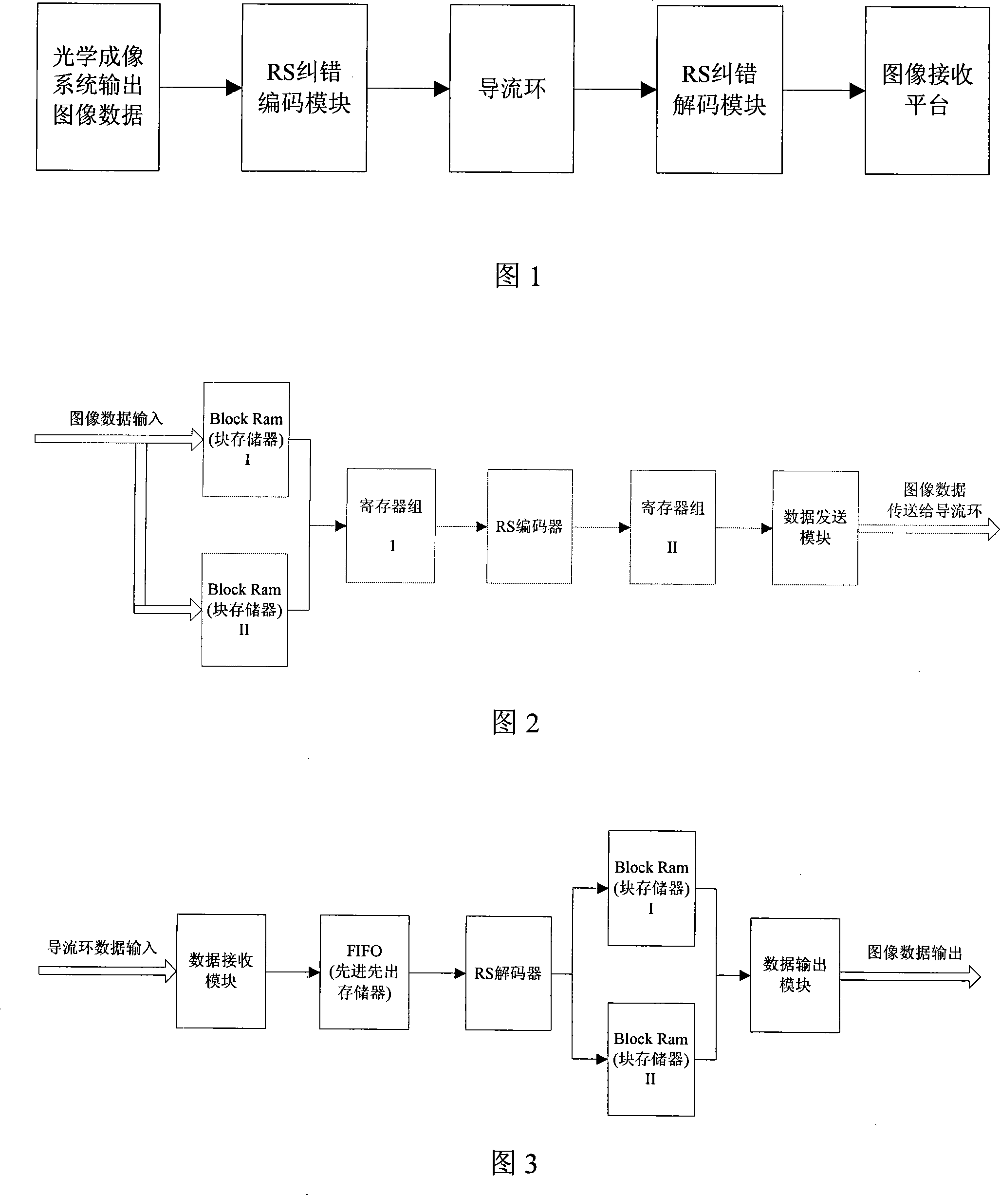
[0017] The image transmitted by the head detector of an omnidirectional infrared imaging system has 292 data per frame, and each data is 14 bits. The first step is to determine the parameters of the RS code. Generally speaking, a more suitable code width is 7 or 5. In this example, out of the consideration of improving the calculation speed as much as possible, we finally determine the code width m=5, that is, each 14-bit data is filled with a zero to make up 15 bits. Then split into three 5-bit data for encoding. After determining m, according to the total code segment length n and formula (2), m=31 can be obtained. After determining m and n, the next step is to determine t and k according to the system error correction performance index. In this omni-directional infrared imaging system, the transmission width of the guide ring is 12 bits, a...


PUM


Abstract

The invention discloses a correction method of deflector ring error code in image transmission of an optical imaging system. The method utilizes RS (Reed Solomon) code as the algorithm of error-correcting code, selects a RS code parameter according to the actual size of transmitted image and the error-correcting requirement, and then designs the relevant error-correcting code and decoding module according to the selected parameter and the transmission characteristic of deflector ring, thereby realizing the correction of deflector ring error code during the image transmission. The invention has the advantages that the invention can efficiently correct the burst error during the image transmission of deflector ring in time, ensure the image data obtained by the optical imaging system to be correctly transmitted to the receiver terminal, and ensure the original image to be restored for the next analysis and treatment.

Description

technical field [0001] The invention relates to the technology of error correction encoding and decoding in image transmission, in particular to a method for correcting code errors of a diversion ring in image transmission, which is applied to an image transmission system of an omnidirectional optical imaging system. Background technique [0002] In an omnidirectional imaging system, such as an omnidirectional infrared imaging system, since the infrared imaging system continuously performs 360° rotating imaging, the acquired images are usually transmitted through a guide ring. The diversion ring is composed of several rings, and each ring transmits one bit of image information. Due to the manufacturing process and long-term mechanical friction, the surface of the guide ring is prone to slight damage or fine dust, which will cause errors in the image data of tens or even hundreds of bits continuously transmitted on a certain ring. If these error codes cannot be corrected in ...

Claims


Application Information

Patent Timeline
Patent Type & Authority Applications(China)
IPC IPC(8): H04N7/64H04N19/89
Inventor 张涌刘文娟赵佳冷寒冰李争陈捷
Owner SHANGHAI INST OF TECHNICAL PHYSICS - CHINESE ACAD OF SCI
Learn More