X-ray imaging equipment and target region indicating method

An imaging device and target area technology, which is applied in the field of medical imaging, can solve the problems of complex operation, inconvenient operation process, and indicating the center position of the image, so as to achieve the effect of simple and accurate operation and convenient treatment process

Active Publication Date: 2018-02-16
SHANGHAI UNITED IMAGING HEALTHCARE
View PDF7 Cites 11 Cited by
  • Summary
  • Abstract
  • Description
  • Claims
  • Application Information

AI Technical Summary

Problems solved by technology

For example, the laser light of the mobile C-arm machine can indicate the center of the image, but since the current laser light can only indicate the center of the image, if you want to indicate the position of the target of interest, you need to adjust the C-arm to adjust the target of interest to the imaging center position, and then indicate the position of the target of interest on the body surface through the laser light
This process is complicated to operate, and the patient needs to be exposed to more radiation during the adjustment process. Due to the inconvenient operation process, it is rarely used clinically.

Method used


Image

  • X-ray imaging equipment and target region indicating method
  • X-ray imaging equipment and target region indicating method
  • X-ray imaging equipment and target region indicating method

Examples


no. 1 example

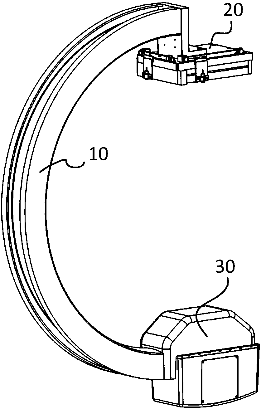
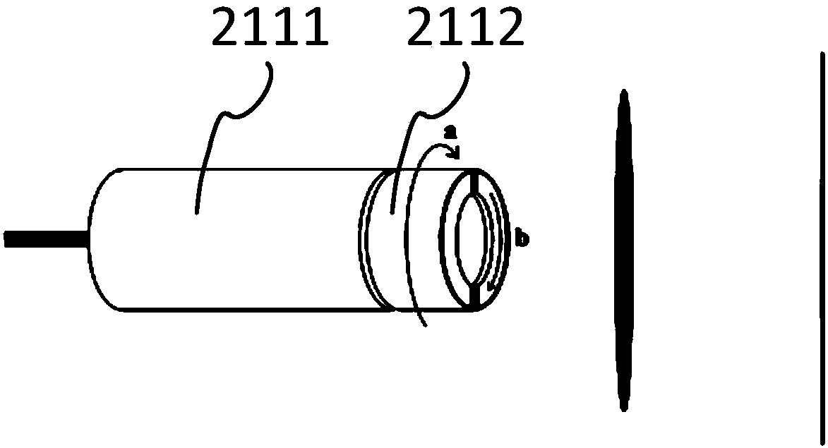
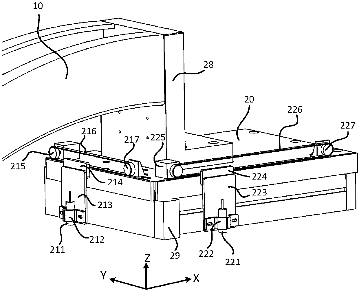
[0050] When the line laser light is used, the target indicator must include at least two laser lights, and the intersection of the two beams of light emitted by the two laser lights is used as the indicated target position. image 3 It is a structural schematic diagram of the target indicator in the first embodiment of the present invention, Figure 4 It is a schematic diagram of the driving process of the target indicator in the first embodiment of the present invention. Such as image 3 , Figure 4 As shown, the C-shaped bracket 10 and the detector 20 are connected by an L-shaped connecting piece 28. The detector 20 includes a rectangular frame, and the first laser lamp 211 and the second laser lamp 221 are located on adjacent two sides of the rectangular frame, respectively. Projecting mutually perpendicular line lights, such as image 3 As shown, the first laser lamp 211 emits a first line of light parallel to the X axis, and the second laser lamp 221 emits a second lin...

no. 2 example

[0054] In this embodiment, a line laser light is also used, and the target area is indicated by the combination of multiple beams of line light. Figure 5 It is a schematic structural diagram of the target indicator of the second embodiment of the present invention, such as Figure 5 The connection mode between the shown C-shaped bracket 10 and the detector 20 is the same as that of the first embodiment, and the structure of the first laser lamp 211, the structure of the second laser lamp 221 and the corresponding drive system structure are also similar to those of the first embodiment, and are not described here. Let me repeat. The difference between this embodiment and the first embodiment is that a third laser lamp 231 and a fourth laser lamp 241 are respectively added on one side of the rectangular frame of the detector where the first laser lamp 211 and the second laser lamp 221 are located. The third and fourth laser lamps 231, 241 also correspond to corresponding drive...


PUM


Abstract

The invention discloses X-ray imaging equipment, which comprises a detector and an X-ray bulb tube which are oppositely arranged; in an imaging process, a to-be-detected object is located between thedetector and the X-ray bulb tube; and the X-ray imaging equipment further comprises a target indicator for indicating the location of a target on the surface of the to-be-detected object. According tothe X-ray imaging equipment provided by the invention, by automatically indicating the position of the target on the surface of the to-be-detected object by virtue of the target indicator, a step oftarget positioning is simplified and residual auxiliary positioning tools are omitted.

Description

technical field [0001] The invention relates to the field of medical imaging, in particular to an X-ray imaging device with a target indicating function and a target indicating method thereof. Background technique [0002] In the early stage of the operation, it is necessary to locate the needle entry point on the body surface or the position of the surgical incision. During the actual operation, although imaging equipment suitable for the operating room such as a mobile C-arm machine was introduced, due to the lack of effective positioning methods, doctors Generally, multiple perspectives have to be performed to find the position of the body surface. For example, in minimally invasive spinal surgery, in order to locate the intervertebral foramen, after the patient is positioned, the doctor takes an iron wire or other imageable fine needle and places it on the body surface near the target area, and observes the iron wire and the fluoroscopy image in the fluoroscopy image. A...

Claims


Application Information

Patent Timeline
Patent Type & Authority Applications(China)
IPC IPC(8): A61B34/20
Inventor 虞倩倩刘文强
Owner SHANGHAI UNITED IMAGING HEALTHCARE
Why Eureka
Try Eureka