Removable partial denture wearing and removing device, matching denture base and use method thereof

A denture base and partial technology, which is applied in the field of removable partial denture wearer, can solve the problem of incompatibility between the specific shape of the force direction of the appliance and the retainer, the product deformation of the appliance and the retainer, and the inability to remove the partial denture. Avoid problems such as denture removal and wear, and achieve the effect of reducing electrochemical corrosion, increasing service life, and enriching functions

Inactive Publication Date: 2018-02-16
SICHUAN UNIV
View PDF6 Cites 2 Cited by
  • Summary
  • Abstract
  • Description
  • Claims
  • Application Information

AI Technical Summary

Problems solved by technology

Compared with the traditional way of picking and wearing, this disclosed technology has made some progress, but there are still many problems. First, the disclosed technology adopts the way of hooking, and the direction of force application is unstable.
During the extraction process, as the hook is pulled at a fixed point, the hooked position is first hooked up, and then other areas are moved upward together. During this process, the hooked position will rotate relatively, making the correction The force direction of the metal ring of the appliance and retainer is deflected, and then the force direction of the appliance and retainer does not correspond to its specific shape, which eventually causes the product deformation of the appliance and retainer, and is not suitable for the removal of removable partial dentures. wore
Secondly, the hook-shaped structure of the hook part used in the disclosed technology of the intraoral dislocation device is easy to scratch the oral mucosa of the patient, and the hook shape has little dislocation force for the clasp attached to the tooth body, and its application is especially for inflexible hands and feet. It is more laborious for people

Method used


Image

  • Removable partial denture wearing and removing device, matching denture base and use method thereof
  • Removable partial denture wearing and removing device, matching denture base and use method thereof
  • Removable partial denture wearing and removing device, matching denture base and use method thereof

Examples


Embodiment Construction

[0030] The present invention will be further explained below in conjunction with the drawings and specific embodiments.

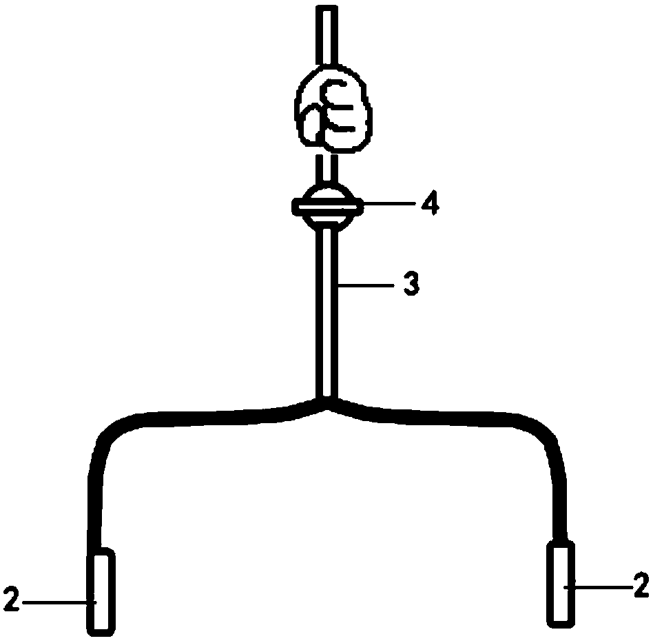
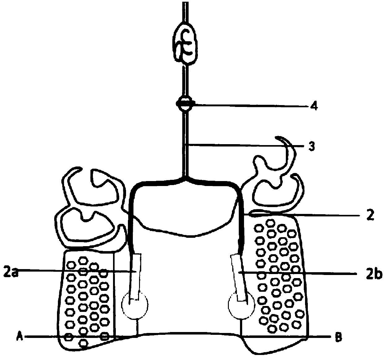
[0031] Such as Figure 1 ~ Figure 5 As shown, this embodiment includes two parts of a removable partial denture remover and a removable partial denture base that cooperate with each other.

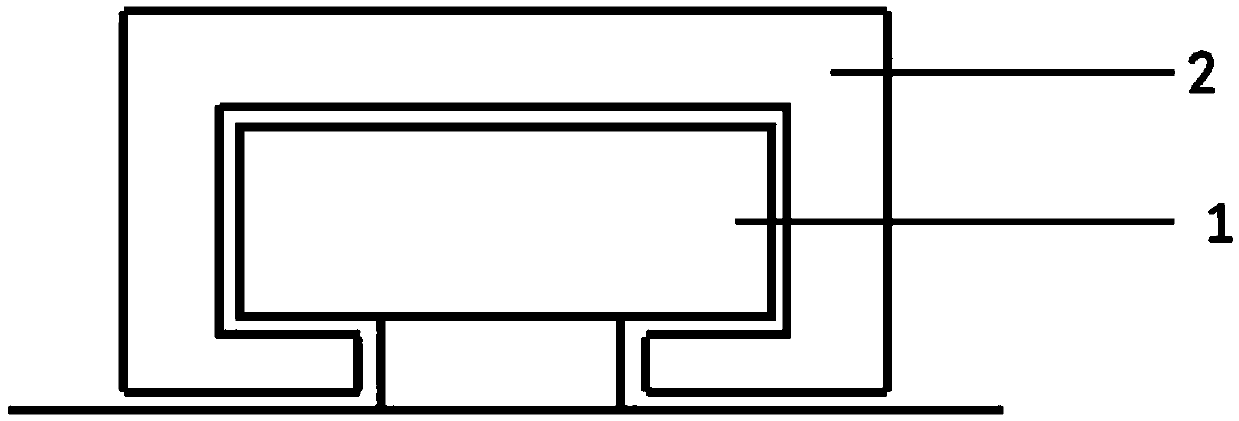
[0032] The removable partial denture base includes a base body, the base body is provided with a buckle protrusion, the buckle protrusion is a "T"-shaped buckle guide rail 1, the buckle guide rail 1 It is arranged along the direction perpendicular to the insertion road in the removable partial denture. The buckle guide rail 1 includes a support base and a slide rail arranged on the top of the support base, and the bottom of the support base is fixedly connected with the base body. The buckle guide rail 1 includes two parts symmetrically arranged on the base body, namely the buckle left guide rail 1a and the buckle right guide rail 1b. The base body and the buckle protrusi...


PUM


Abstract

Belonging to the technical field of stomatologic instruments, the invention in particular provides a removable partial denture wearing and removing device. The removable partial denture wearing and removing device includes a connecting rod and a handle that are interconnected, the connecting rod is equipped with a buckle recess matching a buckle bulge arranged on the removable partial denture base, and the buckle recess is disposed at an end of the connecting rod far from the handle. The invention also correspondingly provides a denture base matching the removable partial denture wearing and removing device and a use method thereof. The removable partial denture wearing and removing device provided by the invention is suitable for crowds lacking self-care ability, transfers a force application area in a denture wearing and removing process to the outside of the oral cavity, also determines the guide rail direction and the handle joint direction through the direction of a denture insertion path, and is convenient for patients to easily complete correct denture wearing and removing actions. The transport power is uniform in the wearing and removing process, and does not cause denturedeformation easily. 3D printing technology or one-piece casting technology is employed to integrate the buckle bulge with the denture metal base into a whole, thus minimizing electrochemical corrosion.

Description

Technical field [0001] The invention belongs to the technical field of oral medical equipment, and specifically relates to a removable partial denture taker, a matching base and a use method thereof. Background technique [0002] For elderly patients with a large number of missing teeth, poor general and local oral conditions, and low tolerance, removable partial dentures have irreplaceable advantages as a repair method with fewer molars, low price, and reversible repair process. . Removable partial dentures enter the undercuts of the remaining teeth through the snap ring to obtain a stable retention in the oral cavity, and avoid the unfavorable undercuts that damage soft and hard tissues during model observation, and design the placement of the denture to make the denture smooth Bit. When removing, a force is applied to the denture in the direction opposite to the in-situ direction of the denture, and the denture is removed from the undercut area through the deformation of the...

Claims


Application Information

Patent Timeline
IPC IPC(8): A61C19/00A61C13/01
CPCA61C13/01A61C19/00
Inventor 朱卓立陈昕张金军
Owner SICHUAN UNIV
Why Eureka
Try Eureka