Aircraft engine lip low-half section drawing forming method

A technology for aircraft engines and forming molds, used in forming tools, metal processing equipment, manufacturing tools, etc., can solve problems such as uneven cross-section change and deformation, poor molding effect, loose edges, etc., to reduce stress relaxation and material processing. Hardening, uniform effect of plastic deformation

Inactive Publication Date: 2018-02-16
XIAN AIRCRAFT IND GROUP
View PDF6 Cites 5 Cited by
  • Summary
  • Abstract
  • Description
  • Claims
  • Application Information

AI Technical Summary

Problems solved by technology

[0004] In order to overcome the defects of the lower half of the engine lip due to the large curvature and cross-section changes, uneven deformation, loose edges, springback, and poor molding effect

Method used


Image

  • Aircraft engine lip low-half section drawing forming method
  • Aircraft engine lip low-half section drawing forming method
  • Aircraft engine lip low-half section drawing forming method

Examples


Embodiment Construction

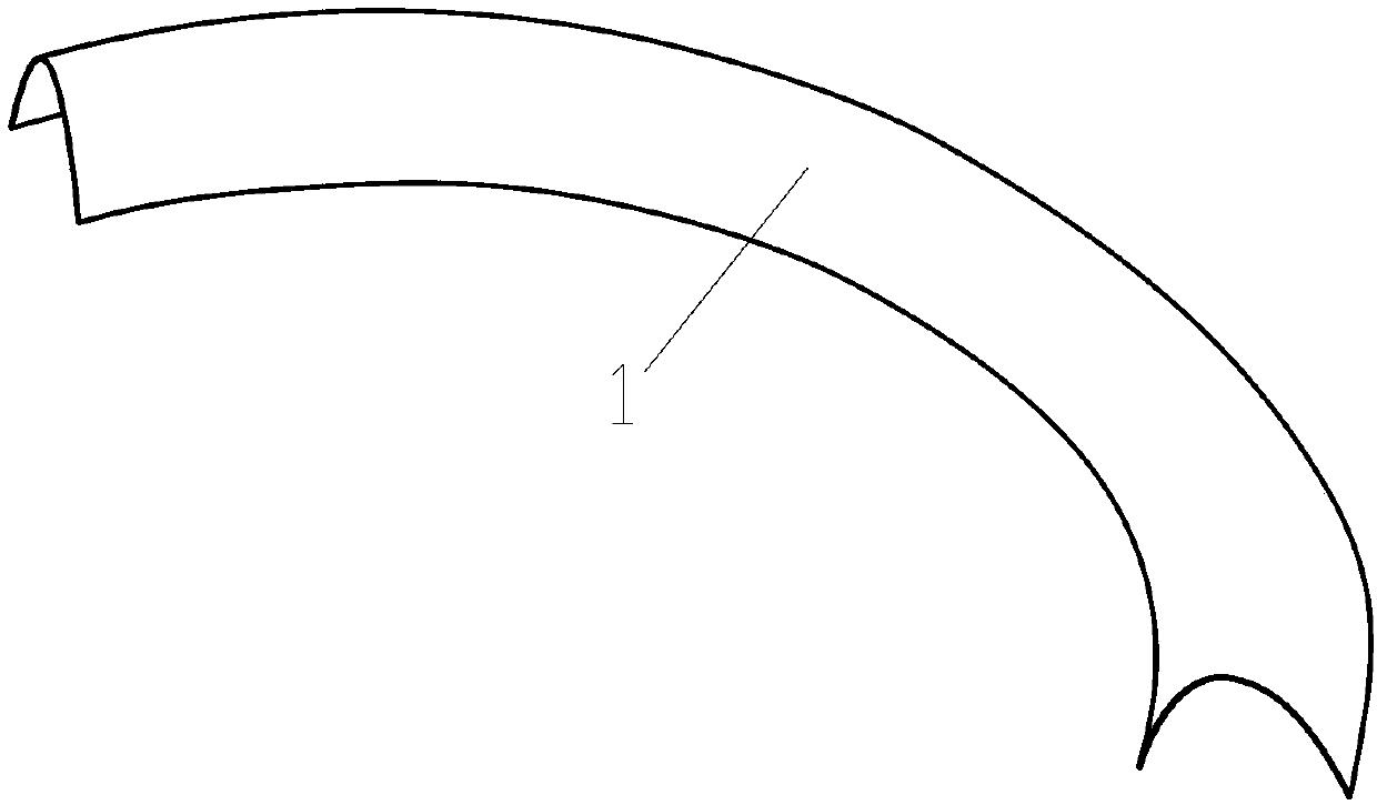
[0020] Refer to attached figure 1 , figure 1 Shown is the theoretical model 1 of the lower half of the aircraft engine lip, its structure is approximately C-shaped and is a parabolic shape with variable cross-section. The existing drawing methods for high-strength materials with variable section and variable curvature shape mainly have the following defects: first, the drawing extension ratio of each section is greatly different, and the degree of deformation is inconsistent, and the forming stress relaxation and edge looseness affect the mold attachment accuracy; second, the material strength is high. , The deformation resistance is large, and the plastic deformation is insufficient, which affects the accuracy of the molding; the third is that the material is deformed and hardened, and the springback caused by unloading stress release is difficult to repair.

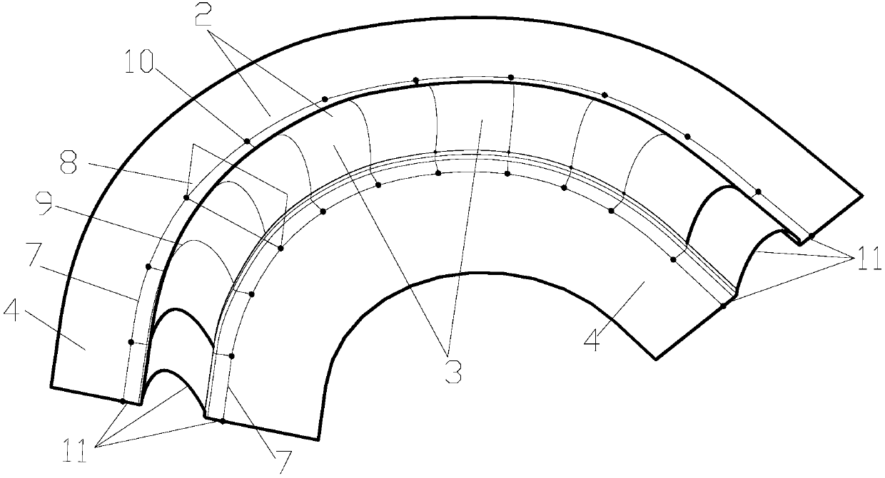
[0021] In order to overcome the forming defects of the lower part of the engine lip above, refer to the attached fi...


PUM


Abstract

The invention relates to an aircraft engine lip low-half section drawing forming method. According to a part theoretical model design drawing forming process model, the process model comprises a convex molded surface and flange edges on the two sides, the upper portion of the convex molded surface is coincident with a part theoretical model, the lower portion of the convex molded surface is an extending supplement face, and the supplement face is composed of a theoretical model tangential extending face and a flange edge vertical extending face; center lines of rolling ribs are designed on theflange edges on the two sides of the process model; a die comprises a female die, edge pressing rings and a male die; the edge pressing rings are matched with the flange edges of the process model, and the upper surfaces of the edge pressing rings are provided with the rolling ribs corresponding to the protruding center lines; the female die is provided with a molding cavity, and a butt joint face of the female die and the edge pressing ring is provided with rolling grooves corresponding to the rolling ribs; and the convex molded surface is the same as a convex molded surface of the process model.

Description

technical field [0001] The application relates to aircraft manufacturing technology, in particular to a deep drawing method, especially suitable for precise die-fitting and deep drawing of the lower half of the lip of a large aircraft engine. Background technique [0002] Due to the influence of complex loads such as high-speed, high-pressure airflow, and resonance in the working environment of aero-engines, the precision of manufacturing and molding of the engine lip that acts as a rectifier is extremely high. In order to meet the requirements of aerodynamic shape, the lip of large aircraft engines is generally designed as a parabolic shape with variable cross-section and smooth transition, and high-strength materials are selected; Forced assembly by stress brings great safety hazard to flight. [0003] In the field of sheet metal deep drawing and forming, improving the precision of high-strength materials has always been the core technology of domestic and foreign automob...

Claims


Application Information

Patent Timeline
Patent Type & Authority Applications(China)
IPC IPC(8): B21D37/20B21D22/20B21D22/22
CPCB21D37/20B21D22/208B21D22/22
Inventor 倪兴屹李善良惠小鹏
Owner XIAN AIRCRAFT IND GROUP
Why Eureka
Try Eureka