
Cutting fluid collecting tank of lathe chip filtering device

A filtering device and cutting fluid technology, applied in metal processing machinery parts, maintenance and safety accessories, metal processing equipment, etc., can solve problems such as no good solution, difficulty in seeing the filtering situation, inconvenient use, etc., and achieve adjustment The irradiation angle is convenient, the lighting effect is good, and the effect is not easy to be blocked

Pending Publication Date: 2018-02-16
平湖智铂自动化设备股份有限公司
View PDF0 Cites 2 Cited by
  • Summary
  • Abstract
  • Description
  • Claims
  • Application Information

AI Technical Summary

Problems solved by technology

[0008] Only for the filtration of chips, there is no good solution for the floating oil in the cutting fluid; and the existing cutting fluid filtering device has a single function, no lighting function, it is difficult to see the filtering situation, and it is inconvenient to use

Method used


Image

  • Cutting fluid collecting tank of lathe chip filtering device
  • Cutting fluid collecting tank of lathe chip filtering device

Examples


Embodiment

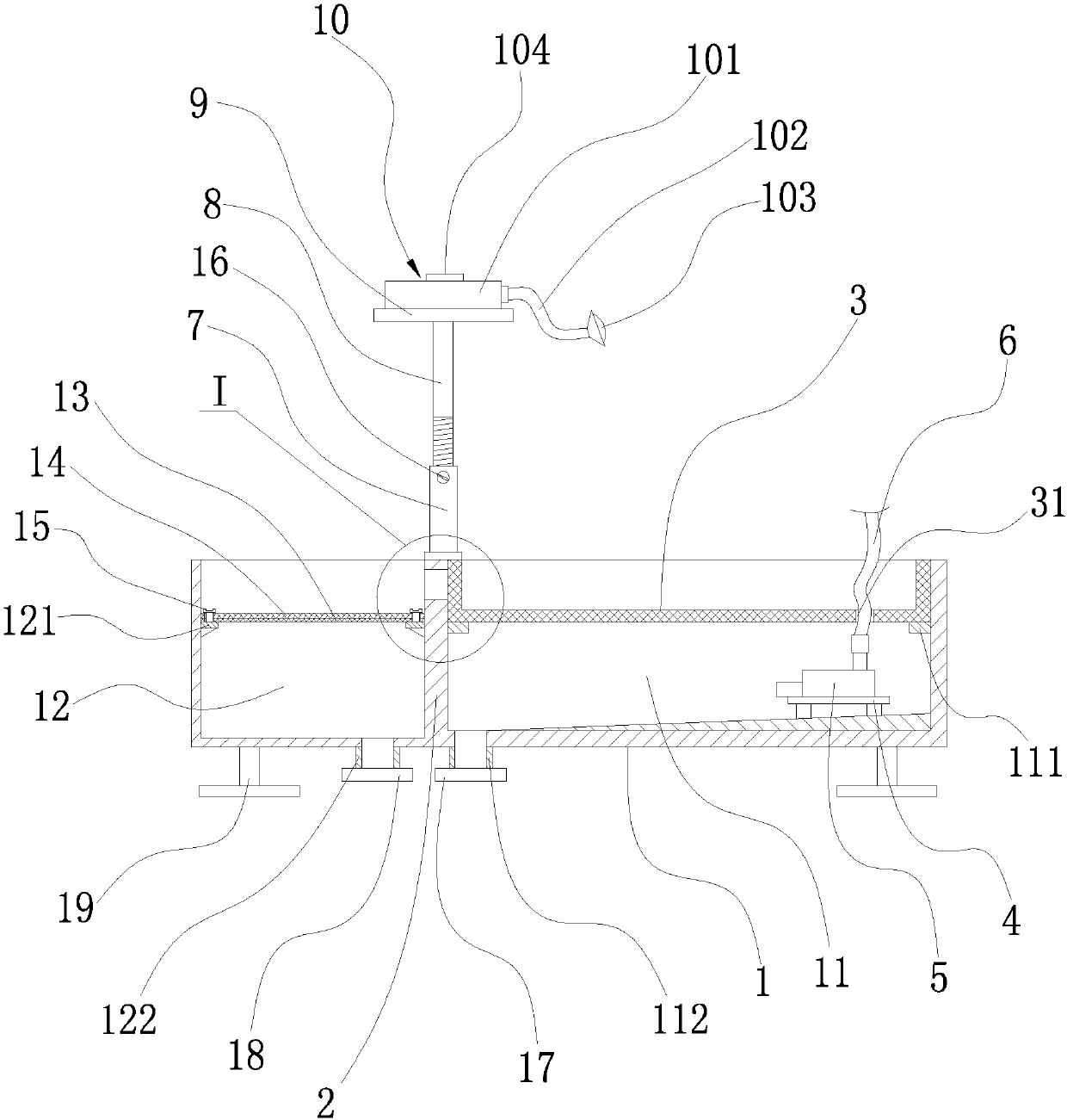
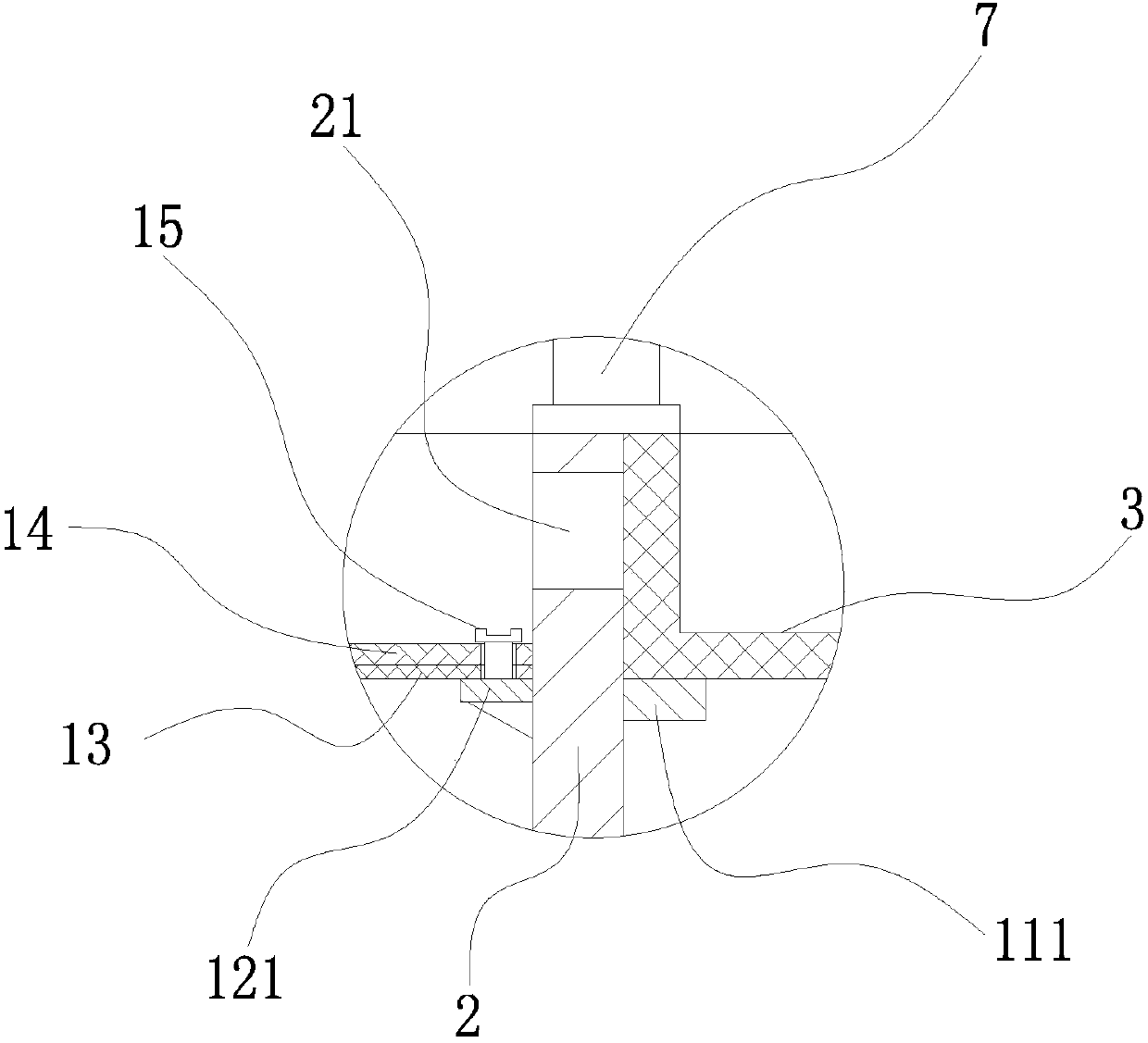
[0027] Example: such as figure 1 with figure 2 As shown, a cutting fluid collection tank of a lathe chip filter device includes a cutting fluid collection tank body 1, a partition plate 2 is integrally arranged in the cutting fluid collection tank body 1, and the cutting fluid collection tank body 1 passes through the partition The plate divides 2 into a first cutting fluid collection chamber 11 and a second cutting fluid collection chamber 12, the upper end of the partition plate 2 is provided with a floating oil outlet 21, and the inner wall of the first cutting fluid collection chamber 11 is integrally provided with A first positioning convex ring 111, a first filter screen 3 is arranged on the first positioning convex ring 111, the inner bottom surface of the first cutting fluid collection chamber 11 is arranged upward from left to right, the first The right end of the inner bottom surface of the cutting fluid collection chamber 11 is fixedly provided with a water pump b...


PUM


Abstract

The invention relates to a cutting fluid collecting tank of a lathe chip filtering device. The cutting fluid collecting tank comprises a cutting fluid collecting tank body; the cutting fluid collecting tank body is separated by a separating plate into a first cutting fluid collecting cavity and a second cutting fluid collecting cavity; a floating oil outlet is formed in the upper end of the separating plate; a first filtering net is arranged on a first positioning bulge ring on the inner wall surface of the first cutting fluid collecting cavity; the inner bottom surface of the first cutting fluid collecting cavity is arranged upwards from left to right; a water pump is detachably arranged on a water pump support at the right end of the inner bottom surface of the first cutting fluid collecting cavity; a vertical supporting pipe is welded at the back end of the cutting fluid collecting tank body; the upper end of the vertical supporting pipe is in threaded connection with an adjusting screw; a lamp panel is welded at the upper end of the adjusting screw; and a lighting device is mounted on the lamp panel. The cutting fluid collecting tank is reasonable in structural design, simple in structure and low in manufacturing cost and has multiple functions, chips mixed in a cutting fluid can be effectively filtered, and floating oil floating in the cutting fluid can be effectively cleared.

Description

technical field [0001] The invention belongs to the technical field of mechanical processing equipment, and in particular relates to a cutting fluid collection tank of a lathe chip filtering device. Background technique [0002] During mechanical processing, it is often necessary to cool the cutting tool and workpiece with cutting fluid. [0003] It will bring the chips generated during processing to the cooling water tank, which will not only easily cause damage to the water pump, flushing pump, pipeline and water spray in the water tank [0004] The nozzle is blocked, which affects the cooling effect, and the cutting fluid mixed with chips is easy to cause secondary cutting on the workpiece, which affects the surface of the workpiece. [0005] Surface processing effect. In addition, during the lubricating process of the machine tool, the lubricating oil will also drip into the cutting fluid. [0006] In addition, it is easy to cause the cutting fluid to deteriorate and ...

Claims


Application Information

Patent Timeline
IPC IPC(8): B23Q11/00B23Q11/10
CPCB23Q11/0075B23Q11/1069
Inventor 李健
Owner 平湖智铂自动化设备股份有限公司
Learn More