Auxiliary suction mechanism for sewage suction truck and sewage suction truck

A technology for sewage suction trucks and sewage pipes, which can be used in waterway systems, water supply devices, buildings, etc., and can solve problems such as blockage of sewage suction pipes

Pending Publication Date: 2018-02-16
FUJIAN LONGMA ENVIRONMENTAL SANITATION EQUIP
View PDF7 Cites 1 Cited by
  • Summary
  • Abstract
  • Description
  • Claims
  • Application Information

AI Technical Summary

Problems solved by technology

[0003] For this reason, it is necessary to provide an auxiliary suction mechanism for a sewage suction truck and a sewage suction truck, which solves the problem of blockage of the sewage suction pipe when vacuuming sewage

Method used


Image

  • Auxiliary suction mechanism for sewage suction truck and sewage suction truck
  • Auxiliary suction mechanism for sewage suction truck and sewage suction truck

Examples


Embodiment 1

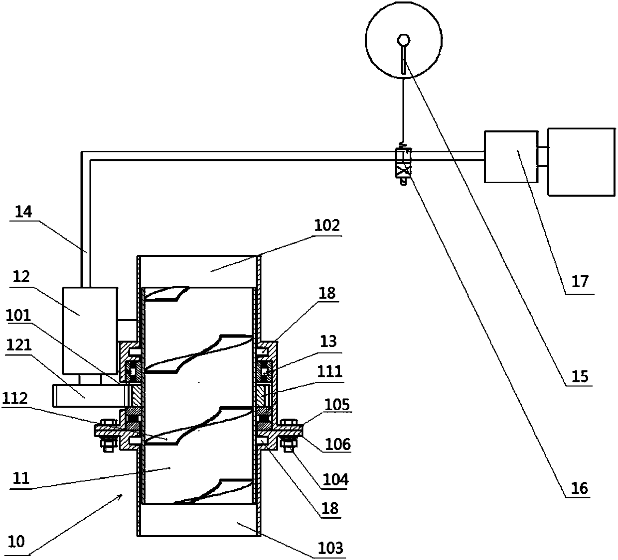
[0038] see figure 1 , this embodiment provides an auxiliary suction mechanism for a sewage suction truck, including an outer cylinder 10, an inner cylinder 11, a hydraulic motor 12, a bearing 13, an oil guide pipe 14, a negative pressure sensor 15, an electromagnetic reversing valve 16 and a gear pump 17 The fuselage of the hydraulic motor is arranged on the outer surface of the outer cylinder, the outer surface of the inner cylinder is provided with outer teeth 111, and the middle part of the outer cylinder is provided with a station hole 101, and the transmission gear 121 of the hydraulic motor is meshed with the outer teeth through the station hole , the bearing is arranged between the outer cylinder and the inner cylinder, and the inner wall of the inner cylinder is provided with a helical blade 112; the oil guide pipe is arranged between the output end of the gear pump and the input end of the hydraulic motor, and the electromagnetic reversing valve is arranged on the oil ...

Embodiment 2

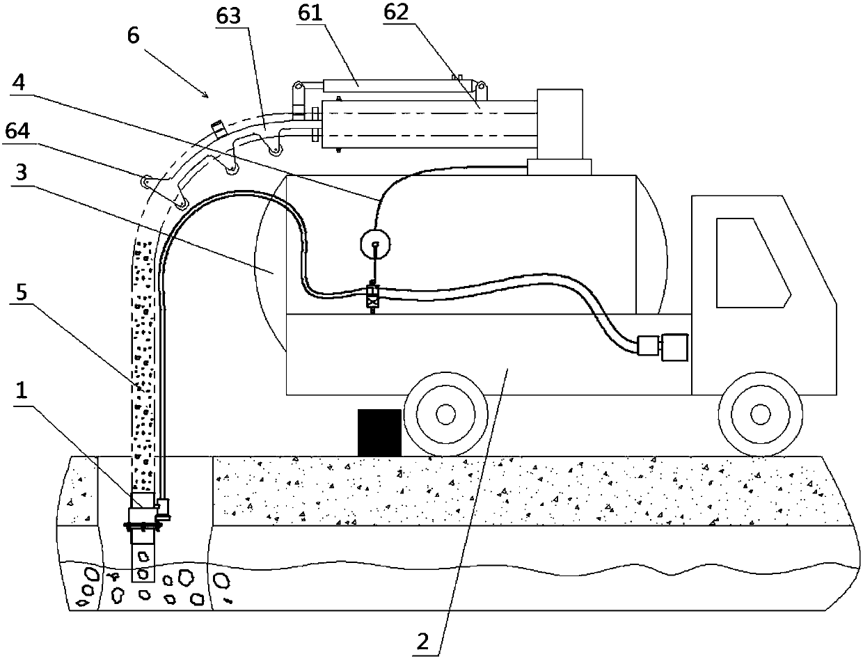
[0045] see figure 2 , this embodiment also provides a sewage suction vehicle with an auxiliary suction mechanism, including an auxiliary suction mechanism 1, a vehicle body 2, a storage tank 3, a vacuum pressure measuring hose 4 and a sewage suction pipe 5; the auxiliary suction The mechanism is the auxiliary suction mechanism described in any one of claims 1 to 5; the storage tank is arranged on the vehicle body of the car body, and the vacuum pressure measuring hose is connected between the storage tank and the negative pressure sensor to assist the suction. The mechanism is arranged at the inlet end of the sewage suction pipe, the outlet end of the sewage suction pipe is connected to the feed port of the storage tank, and the gear pump of the auxiliary suction mechanism is arranged on the power take-off of the car body. The power take-off for the car body is composed of one or more sets of speed change gears, also known as power output devices, which are generally composed...


PUM


Abstract

The invention provides an auxiliary suction mechanism for a sewage suction truck and the sewage suction truck. The mechanism comprises an outer cylinder, an inner cylinder, a hydraulic motor, a bearing, an oil conduit, a negative pressure transducer, an magnetic exchange valve and a gear pump, external teeth are arranged on the outer side surface of the inner cylinder, a work station hole is formed in the middle of the outer cylinder, and a helical blade is arranged on the inner wall of the inner cylinder. When a sewage suction pipe sucks blocky deposits, medium resistance in the sewage suction pipe can be increased, the suction speed of the sewage suction truck is slowed down, and even the blocking and stagnation situations are likely to occur. When the value obtained by the negative pressure transducer reaches a preset value, the auxiliary suction mechanism is started, the helical blade in the inner cylinder rotates, the blocky deposits are crushed, and the blocky deposits are suckedvery hard to be pushed into a storage tank. Therefore, the work efficiency of suction of the sewage suction truck is improved, the blocky deposits can be crushed effectively through the auxiliary suction mechanism, the phenomenon that the sewage suction pipe is blocked is prevented, the problem that a vacuum pump is too heat is avoided, and the service life of the vacuum pump is prolonged.

Description

technical field [0001] The invention relates to the field of garbage cleaning devices, in particular to an auxiliary suction mechanism of a sewage suction vehicle and the sewage suction vehicle. Background technique [0002] At present, domestic sewage suction trucks generally use the principle of vacuum negative pressure suction to suck sewage, that is, first use a vacuum pump to evacuate the tank body, and then use atmospheric pressure to press the liquid sewage into the tank body through the sewage suction pipe, so as to achieve suction. purpose of sewage. Among them, the sewage suction pipe is connected between the tank body of the sewage suction truck and the sewage, and then the sewage is sucked into the tank body, and the sewage suction process will be limited by the atmospheric pressure, so when the suction medium is relatively viscous, When the density is high or when the large lumpy sludge is sucked, the speed of vacuum suction will slow down, and the sewage sucti...

Claims


Application Information

Patent Timeline
Patent Type & Authority Applications(China)
IPC IPC(8): E03F7/10
CPCE03F7/10E03F7/106
Inventor 林春玮邹震黄耀武郭锦鹏赖建文
Owner FUJIAN LONGMA ENVIRONMENTAL SANITATION EQUIP
Why Eureka
Try Eureka