Construction method of prefabricated part and cast-in-place column assembly integral concrete frame structure

A technology of frame structure and cast-in-place columns, which is applied in the direction of building construction and construction, can solve the problems of low seismic performance and achieve the effects of improved seismic performance, improved construction efficiency, and improved integrity

Inactive Publication Date: 2018-02-16
ZHEJIANG ZHANCHENG CONSTR GROUP
View PDF6 Cites 9 Cited by
  • Summary
  • Abstract
  • Description
  • Claims
  • Application Information

AI Technical Summary

Problems solved by technology

[0004] The present invention aims at the deficiencies of the low seismic performance of the existing prefabricated concrete structures, and provides a construction method for assembling an integral concrete frame structure with prefabricated parts and cast-in-place columns. Construction Efficiency

Method used


Image

  • Construction method of prefabricated part and cast-in-place column assembly integral concrete frame structure
  • Construction method of prefabricated part and cast-in-place column assembly integral concrete frame structure
  • Construction method of prefabricated part and cast-in-place column assembly integral concrete frame structure

Examples


Embodiment 1

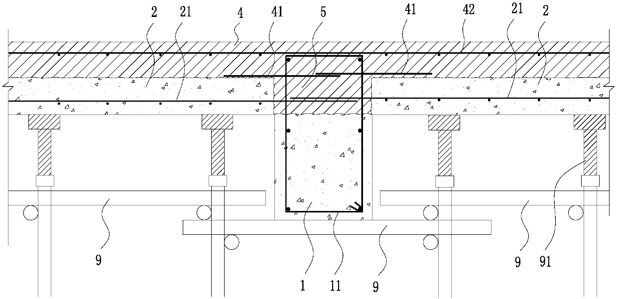
[0053] see Figure 1 to Figure 5, the construction method of prefabricated parts and cast-in-situ columns assembling integral concrete frame structure of the present invention, comprises the following steps:

[0054] S1. Preparation of prefabricated parts, the prefabricated parts include prefabricated beams and prefabricated slabs, and the ends of the prefabricated beams and prefabricated slabs are provided with tendons;

[0055] S2. Site leveling, measurement and setting out;

[0056] S3. Bracket erection;

[0057] S4. Hoisting of prefabricated parts;

[0058] S5. Binding of steel bars, binding the beard bars of prefabricated beams and prefabricated slabs with the steel bars of cast-in-place columns;

[0059] S6. The concrete is poured to form a cast-in-place column, and the cast-in-place column and the prefabricated part are poured as one;

[0060] S7. Conservation.

[0061] In the construction method of prefabricated parts and cast-in-place columns assembling an integr...

Embodiment 2

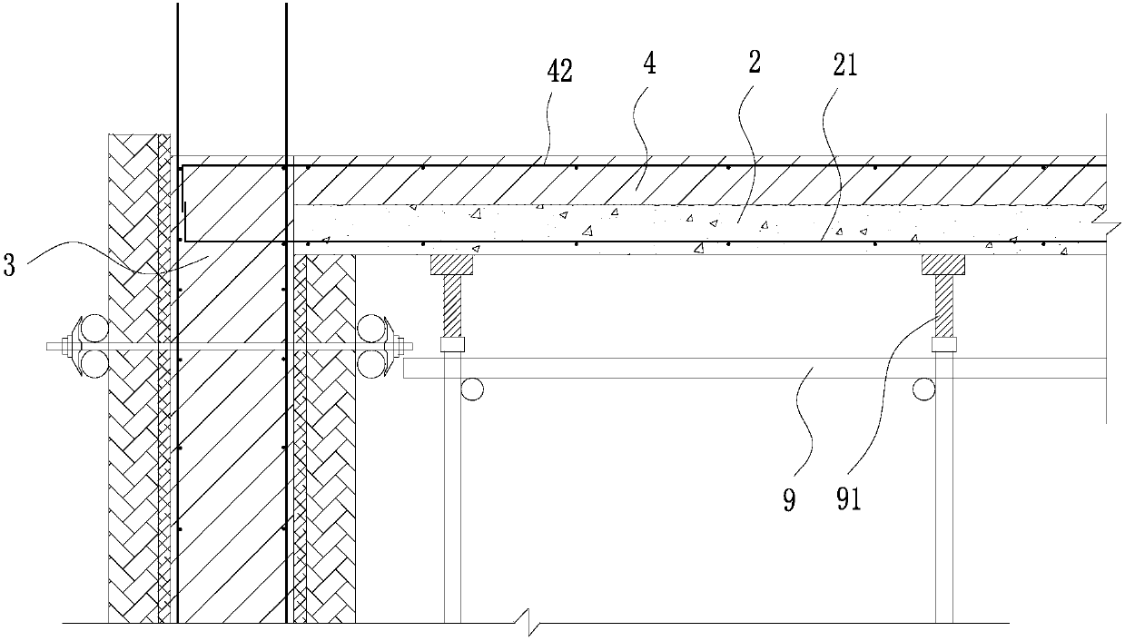
[0090] see Figure 6 , In this embodiment, only the use of cast-in-situ columns, prefabricated beams, and prefabricated slabs is limited, and there is no restriction on the stairs, and there is no restriction on whether to re-cast the floor slab.

Embodiment 3

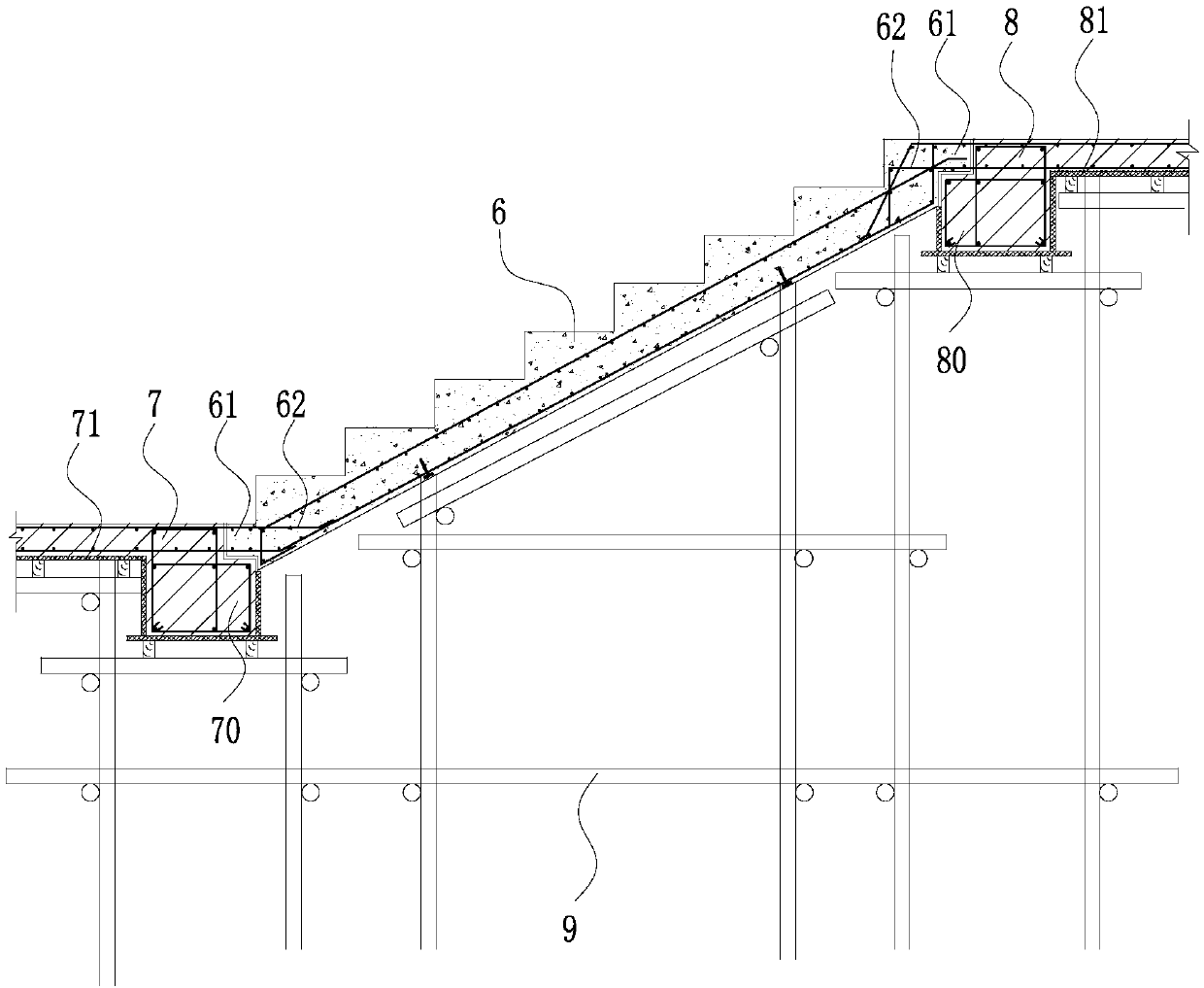
[0092] see Figure 7 , in this embodiment, it is limited to cast-in-place floor slabs in addition to prefabricated beams and prefabricated slabs. In step S6, the concrete is poured to form a cast-in-place column and a cast-in-place floor slab, and prefabricated slabs are placed on both sides of the upper surface of the prefabricated beam, the upper surface of the prefabricated beam is aligned with the lower surface of the prefabricated slab, and the pouring of the cast-in-place beam is formed above the prefabricated beam space.


PUM


Abstract

The invention belongs to the technical field of prefabricated concrete structural design and construction, and particularly relates to a construction method of a prefabricated part and a cast-in-placecolumn assembly integral concrete frame structure. In order to overcome the defect that an existing assembly concrete structure is poor in seismic resistance, the technical scheme is adopted, the construction method of the assembly integral concrete frame structure comprises the following steps that S1, a prefabricated part is prepared, and the prefabricated part comprises a prefabricated beam and a prefabricated plate; S2, leveling, measuring and setting-out are conducted on a site; S3, a support is set up; S4, the prefabricated part is hoisted; S5, reinforcement assembling is conducted, andassembling is conducted on horizontal reinforcing bars of the prefabricated beam and the prefabricated plate and reinforcing steel bars of a cast-in-place column; S6, concrete is poured to form the cast-in-place column, and the cast-in-place column and the prefabricated part are poured into a whole; and S7, maintenance is conducted. The construction method gives consideration to both of the structural seismic resistance and the construction high efficiency.

Description

technical field [0001] The invention belongs to the technical field of prefabricated concrete structure design and construction, and in particular relates to a construction method for assembling an integral concrete frame structure with prefabricated parts and cast-in-place columns. Background technique [0002] The industrialization of construction is the main direction of the transformation and upgrading of the construction industry in my country at this stage. The prefabricated concrete structure is an important part of the industrialization of construction. It has many advantages such as good component quality, short construction period, less resource use and production waste, and has gradually become the development trend of the industry. [0003] In the existing prefabricated concrete structure, its prefabricated columns, prefabricated beams, prefabricated slabs, prefabricated stairs and other components are prefabricated in the factory, and transported to the construct...

Claims


Application Information

Patent Timeline
Patent Type & Authority Applications(China)
IPC IPC(8): E04B1/00
CPCE04B1/00
Inventor 吴建挺陆其荣孙向红王健赵勇赵杭波朱巍祝德江杨佳佳郭于玮
Owner ZHEJIANG ZHANCHENG CONSTR GROUP
Why Eureka
Try Eureka