Civil engineering damping device

A shock absorbing device and civil engineering technology, which is applied in the direction of earthquake resistance, building components, building types, etc., can solve problems such as earthquakes are difficult to predict, and achieve the effects of reducing vibration, saving costs, and maintaining stability

Inactive Publication Date: 2018-02-16
NORTH CHINA UNIV OF WATER RESOURCES & ELECTRIC POWER
View PDF3 Cites 6 Cited by
  • Summary
  • Abstract
  • Description
  • Claims
  • Application Information

AI Technical Summary

Problems solved by technology

However, due to the randomness and suddenness of earthquakes,

Method used


Image

  • Civil engineering damping device
  • Civil engineering damping device

Examples


Embodiment 1

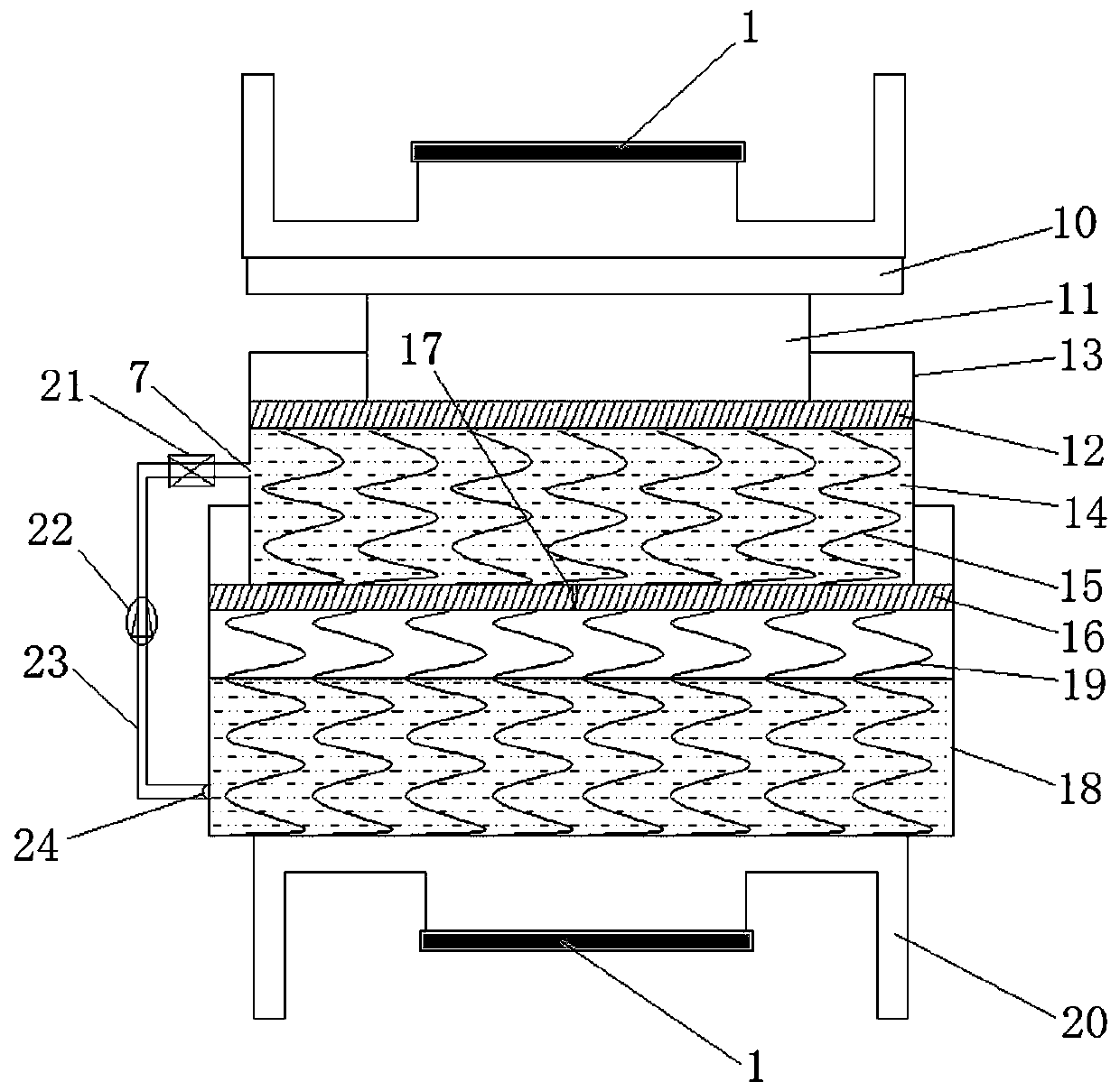
[0030] Such as figure 1 The shown civil engineering damping device includes an upper deck 8 and a lower deck 20 symmetrically arranged up and down, and a shock absorbing assembly installed between the upper deck 8 and the lower deck 20, and the shock absorbing assembly is from top to bottom. A support platform 10, a push rod 11 and a hydraulic cylinder are arranged in sequence below, the upper end of the support platform 10 is connected with the upper deck 8, and the lower end of the support platform 10 is fixedly connected with the upper end of the push rod 11.

[0031] Wherein, the hydraulic cylinder includes a primary hydraulic cylinder 13, a secondary hydraulic cylinder 18, and a primary piston 12 and a secondary piston 16 located in the corresponding hydraulic cylinder; the primary hydraulic cylinder 13 is fixedly connected to the ejector rod through the primary piston 12 11, the primary hydraulic cylinder 13 below the primary piston 12 is filled with hydraulic oil 14; th...

Embodiment 2

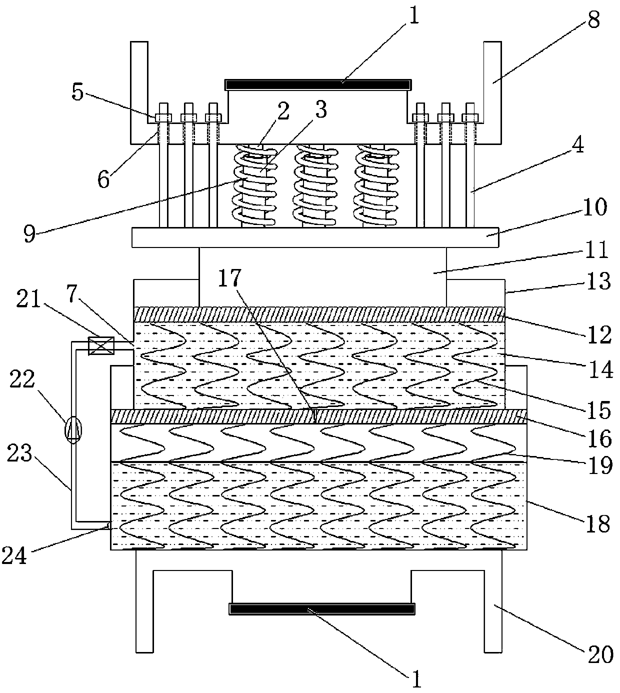
[0039] Such as figure 2As shown, a civil engineering shock absorbing device is different from Embodiment 1 in that an elastic buffer assembly is fixed between the upper deck 8 and the support platform 10, and the rest are the same as Embodiment 1.

[0040] Wherein, the elastic buffer assembly includes a buffer unit and a vertical bolt 4 fixed on the support platform 10. The buffer unit includes a ferrule 3, a compression spring 9, and a clamping column 2 sleeved in the ferrule 3. The upper end of the clamping column 2 It is fixedly connected with the upper deck 8, the lower end of the ferrule 3 is fixedly connected with the support platform 10, and the clamping column 2 and the ferrule 3 are sleeved with a compression spring 9; The upper end of the vertical bolt 4 passing through the screw hole 6 is fixed with a nut to control the maximum displacement of the upper card seat 8 rebounded by the elastic buffer assembly to protect the shock absorber from being rebounded by the el...


PUM


Abstract

The invention discloses a civil engineering damping device which aims to solve the technical problems that an existing damping device is single in damping system and the damping effect is poor. The damping device comprises an upper clamping seat, a lower clamping seat and a damping assembly. The damping assembly sequentially comprises a supporting table, a jacking rod and hydraulic cylinders fromtop to bottom. The lower end of the jacking rod is connected with the first level hydraulic cylinder through a first level piston. The first level hydraulic cylinder is arranged in the second level hydraulic cylinder by serving as the second level jacking rod, and the first level hydraulic cylinder is connected with a second level piston of the second level hydraulic cylinder. A plurality of firstlevel springs are connected to the position between the first level piston and the first level hydraulic cylinder. A plurality of second level springs are connected to the position between the secondlevel piston and the second level hydraulic cylinder. A damping hole communicating with the second level hydraulic cylinder is formed in the center of the second level piston, and the first level hydraulic cylinder is connected with the second level hydraulic cylinder through an oil conveying pipeline. According to the civil engineering damping device, multiple buffering systems are arranged so that the buffering effect can be obviously enhanced, the seismic energy can be effectively absorbed and consumed sufficiently, and thus the safety between engineering buildings is ensured.

Description

technical field [0001] The invention relates to a shock absorbing device, in particular to a civil engineering shock absorbing device. Background technique [0002] Earthquake is one of the unavoidable natural disasters in human society. The casualties and economic losses caused by earthquakes amount to 90%, and even more are caused by the collapse of buildings. Therefore, all countries in the world are devoting themselves to doing a good job in earthquake resistance and disaster reduction of construction projects, and are committed to improving the anti-seismic fortification level of construction projects and improving the anti-seismic capacity of construction projects. However, due to the randomness and suddenness of earthquakes, it is difficult for people to accurately predict earthquakes. [0003] The traditional seismic design method of structures relies on increasing the strength and deformation capacity of the structure itself to resist earthquakes. At this time, a l...

Claims


Application Information

Patent Timeline
IPC IPC(8): E04B1/98E04H9/02
CPCE04H9/021E04H9/0235
Inventor 陈渊召李振霞
Owner NORTH CHINA UNIV OF WATER RESOURCES & ELECTRIC POWER
Why Eureka
Try Eureka