
Steel structure roof and mounting method thereof

A technology of steel structure and mounting holes, which is applied to roofs, building components, building structures, etc., can solve problems such as heavy workload, save labor costs, and avoid position deviation.

Active Publication Date: 2018-02-16
江西佳慧钢结构工程有限公司
View PDF5 Cites 6 Cited by
  • Summary
  • Abstract
  • Description
  • Claims
  • Application Information

AI Technical Summary

Problems solved by technology

However, when installing a steel structure roof, it is necessary to use multiple fixing bolts to lock the roof on the ring beam. When locking the fixing bolts, with the locking of a certain fixing bolt, it will be caused by the stress and deformation of the roof steel structure. The first through holes and threaded holes that cooperate with each other are staggered, so when locking the fixing bolts, multiple workers are required to lock the fixing bolts at different positions at the same time, or workers are required to lock the fixing bolts at different positions in a staggered manner, resulting in heavy workload

Method used


Image

  • Steel structure roof and mounting method thereof
  • Steel structure roof and mounting method thereof
  • Steel structure roof and mounting method thereof

Examples


Embodiment Construction

[0021] The standard parts used in the present invention can be purchased from the market, the special-shaped parts can be customized according to the description in the description and the drawings, and the specific connection methods of each part are all mature bolts, rivets, welding in the prior art. , pasting and other conventional means will not be described in detail here.

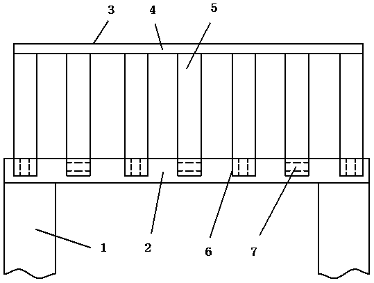
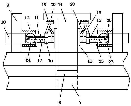
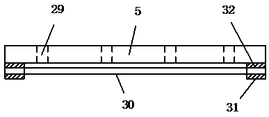
[0022] refer to Figure 1-5 , a specific embodiment of the present invention includes a steel column beam 1 and a ring beam 2 fixedly connected with the steel column beam 1, the ring beam 2 is connected with a top beam 3, and the top beam 3 includes a beam ridge 4 and is welded on the beam ridge 4. The beam arms 5 on both sides, the ring beam 2 is provided with a slot 6 corresponding to the beam ridge 4 one-to-one, the slot 6 is provided with a threaded hole 7, and the beam ridge 4 is provided with a one-to-one corresponding to the threaded hole 7. A through hole 8; the outer side of the threaded hol...


PUM


Abstract

The invention discloses a steel structure roof comprising steel column beams and ring beams fixedly connected with the steel column beams. Top beams are connected to the ring beams and comprise beam ridges and beam arms welded to the two sides of the beam ridges. Inserting grooves corresponding to the beam ridges in a one-to-one mode are formed in the ring beams, threaded holes are formed in the inserting grooves, and first through holes corresponding to the threaded holes in a one-to-one mode are formed in the beam ridges. A bolt positioning mechanism is fixed to the outer sides of the threaded holes and comprises an outer sleeve fixed to the inserting grooves, two sliding rods are symmetrically connected to the side wall of the outer sleeve in a threaded mode, and connecting columns arein shaft connection with the ends of the inner sides of the sliding rods. First spring bodies are connected between the connecting columns and the outer sleeve, arc-shaped clamping plates are hinged to the connecting columns, and threaded parts are arranged on the inner side faces of the arc-shaped clamping plates and engaged with fixing bolts inserted into the threaded holes and the first throughholes. According to the steel structure roof, the defects in the prior art can be improved, and the mounting process of the steel structure roof is simplified.

Description

technical field [0001] The invention relates to the technical field of construction, in particular to a steel structure roof and an installation method thereof. Background technique [0002] In recent years, my country's construction industry has developed rapidly. Traditional reinforced concrete buildings have high energy consumption and high pollution in the construction process, while steel structure buildings have low energy consumption and short construction period, which is a better building structure. . However, when installing a steel structure roof, it is necessary to use multiple fixing bolts to lock the roof on the ring beam. When locking the fixing bolts, along with the locking of a fixing bolt, it will be caused by the stress and deformation of the roof steel structure. The other first through holes and threaded holes that cooperate with each other are staggered, so when locking the fixing bolts, multiple workers are required to lock the fixing bolts at differen...

Claims


Application Information

Patent Timeline
IPC IPC(8): E04B7/00E04G21/14
Inventor 张海江
Owner 江西佳慧钢结构工程有限公司
Learn More