Annular pressure downhole control valve

An annular pressure and control valve technology, which is applied in wellbore/well valve devices, drilling equipment, wellbore/well components, etc., can solve the problems of increased drilling costs, unsuitable pressure regulation, and increased difficulty in construction operations. To achieve the effect of convenient installation and construction procedures, improved service life and safety performance, and simple structure

Pending Publication Date: 2018-02-16
CHINA UNIV OF PETROLEUM (BEIJING)
View PDF6 Cites 12 Cited by
  • Summary
  • Abstract
  • Description
  • Claims
  • Application Information

AI Technical Summary

Problems solved by technology

[0004] The above deep-water casing high-pressure spring pressure relief valve is suitable for adjusting the pressure in the inner annular space of a single casing because it uses external threads to connect with the casing inner wall to control the pressure on both sides of the casing, but for the pressure between multiple casings Adjustment cannot be applied
However, measures commonly used in engineering applications, such as returning the annular cement to the wellhead and adding compressible liquid in the sealed annulus, will bring about a corresponding increase in drilling costs and difficulty in construction operations.

Method used


Image

  • Annular pressure downhole control valve
  • Annular pressure downhole control valve
  • Annular pressure downhole control valve

Examples


Embodiment Construction

[0033] The present invention will be further described in detail below in conjunction with the accompanying drawings and embodiments. It should be understood that the specific embodiments described here are only used to explain the present invention, but not to limit the present invention. In addition, it should be noted that, for the convenience of description, only some structures related to the present invention are shown in the drawings but not all structures.

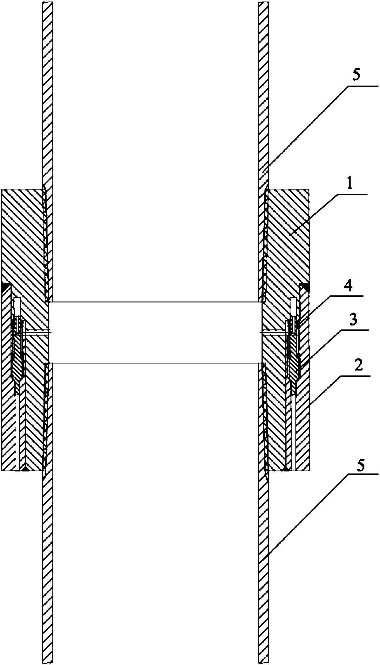
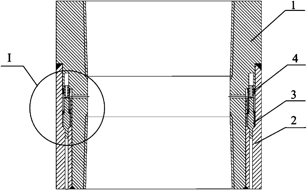
[0034] Such as figure 1 As shown, the present invention provides an annulus pressure downhole control valve, which includes a coupling 1 and an outer cylinder 2 that is mated with the coupling 1. The coupling 1 and the outer cylinder 2 cooperate to form a first accommodating chamber and a second accommodating chamber. chamber, the first housing chamber communicates with the sleeve 5, and the second housing chamber communicates with the outside of the first housing chamber and the sleeve 5 respectively to form a on...


PUM


Abstract

The invention discloses an annular pressure downhole control valve, and belongs to the technical field of oil-gas well engineering. The annular pressure downhole control valve is designed to solve theproblem of annular pressure anomaly in an oil-gas well. The annular pressure downhole control valve comprises a coupling and an outer cylinder which is in fit connection with the coupling; the coupling and the outer cylinder are matched to form a first accommodating cavity and a second accommodating cavity, the first accommodating cavity communicates with a casing pipe, and the second accommodating cavity communicates with the exteriors of the first accommodating cavity and the casing pipe to form a one-way flow channel; and the second accommodating cavity is internally provided with a valvecore which can move along the inner wall of the second accommodating cavity to open or close the one-way flow channel. According to the annular pressure downhole control valve, the abnormal annular pressure in oil-gas well completion and production engineering can be alleviated, integrity and production safety of a wellbore are ensured, the structure is simple, the machining cost is low, and the cost of controlling the annular pressure can be effectively reduced.

Description

technical field [0001] The invention relates to the technical field of oil and gas well engineering, in particular to an annular pressure downhole control valve. Background technique [0002] During the drilling and completion process, in order to separate different geological formations and prevent the well wall from collapsing due to different geological formations, one or more layers of casing are required for cementing, and the annular space between the casings that is not cemented is formed. The annular space is filled with liquids of different properties. In the production process of oil or natural gas, etc., the radial heat transfer of the circulating fluid in the well will cause the thermal expansion of the annular fluid and the casing string, which will cause the expansion and pressurization of the annular fluid, resulting in abnormal annular pressure. With the deepening of exploration and development of high temperature and high pressure oil and gas wells and deep...

Claims


Application Information

Patent Timeline
Patent Type & Authority Applications(China)
IPC IPC(8): E21B33/13E21B34/06E21B17/02
CPCE21B17/02E21B33/13E21B34/06
Inventor 王宴滨高德利房军曾静
Owner CHINA UNIV OF PETROLEUM (BEIJING)
Why Eureka
Try Eureka