Jet flow control-type fertilization pump

A technology for jet control and fertilization pumps, which is applied to jet pumps, fertilization devices, non-volume pumps, etc., can solve the problems of high piston movement resistance, poor sealing between piston and cylinder, and impossibility to achieve increased stability and increased Sealing, drag reduction effect

Inactive Publication Date: 2018-02-16
JIANGSU UNIV
View PDF7 Cites 1 Cited by
  • Summary
  • Abstract
  • Description
  • Claims
  • Application Information

AI Technical Summary

Problems solved by technology

[0004] In order to solve the problem of unstable switching of the jet wall in the jet space when the water flow is direct, it is impossible to smoothly switch the flow into the drive chamber and the reset chamber in the left and right outlet channels, and the sealing between the piston and the cylinder is poor, and the movement resistance of the piston is large, so it cannot be realized Effective fertilizer suction and fertilizer injection state, providing a jet-controlled fertilization pump with reliable jet flow reversing, good sealing between piston and cylinder, and using jet flow wall switching technology to drive piston movement

Method used


Image

  • Jet flow control-type fertilization pump
  • Jet flow control-type fertilization pump
  • Jet flow control-type fertilization pump

Examples


Embodiment Construction

[0034] For doing further understanding to the present invention, now in conjunction with accompanying drawing, the present invention is described further:

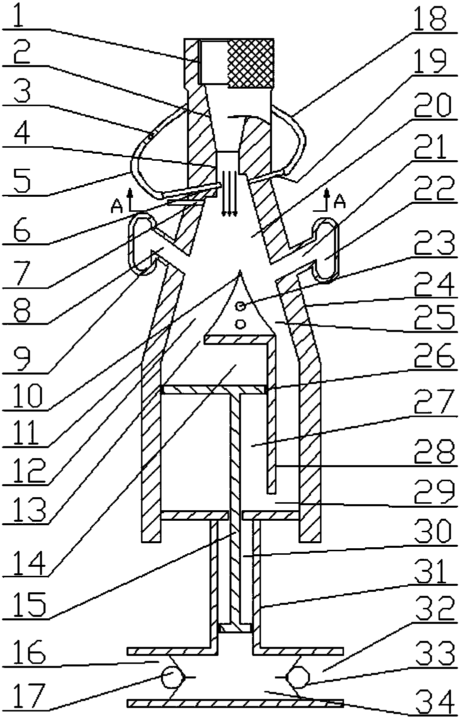
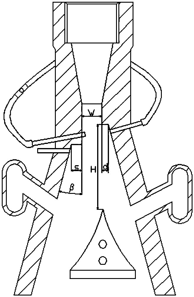
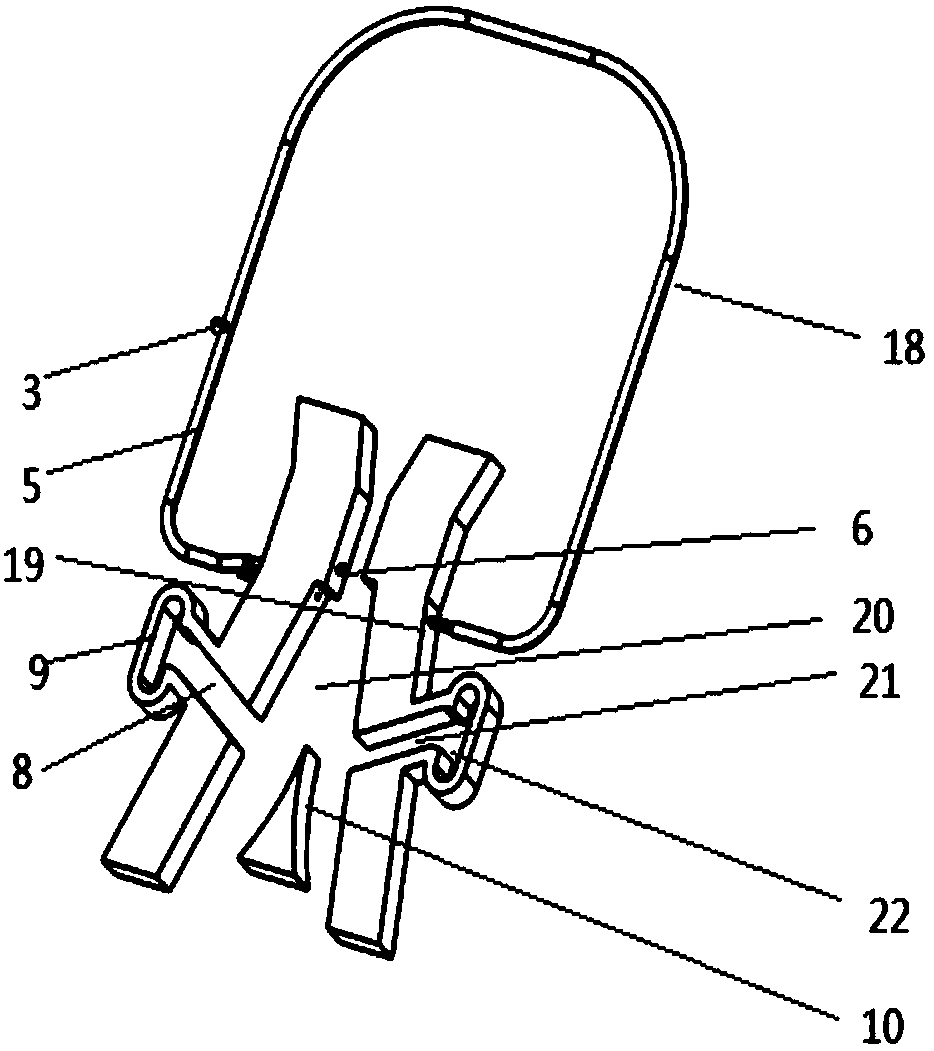
[0035] combined with figure 1 , figure 2 , image 3 , Figure 4 with Figure 5, the jet control fertilization pump includes a jet element, a water intake nozzle 6, a left rubber conduit 5, an air supply tee pipe 3, a right rubber conduit 18, a water inlet 19, a reverse air supply hole 7, a piston assembly 15 and a cylinder 31; The jet element includes a threaded inlet 1, a contraction section 2, a guide section 4, a jet space 20, a left emptying channel guiding section 8, a left emptying channel outlet 9, a right emptying channel guiding section 21, a right Evacuation channel outlet 22, left output channel 12, right output channel 25, propulsion chamber inlet 13, reset chamber inlet 29; the front end of the jet element is threaded inlet 1, threaded inlet 1 is connected to shrinkage section 2, and shrinkage section 2 i...


PUM


Abstract

The invention discloses a jet flow control-type fertilization pump, and relates to the field of fluid machines. The jet flow control-type fertilization pump comprises a water collecting nozzle, a leftrubber guide pipe, an air make-up t-branch pipe, a reverse air make-up hole, a right rubber guide pipe, a water inlet nozzle, a jet flow component including a movable wedge and a draining channel, ahydraulic cylinder and a piston. The hydraulic cylinder system is divided into a driving cavity, a reset cavity, a buffer cavity and a fertile solution cavity through the piston. The outlet section ofthe jet flow component is divided into two outlet flow channels through the movable wedge. The left side flow channel communicates with the driving cavity, and the right side flow channel communicates with the reset cavity. The draining channel is used for discharging return water in the fertilization pump. The reverse air make-up hole supplements air of a left cavity to form the pressure difference so that jet flow can be attached to the right side wall face. The water inlet nozzle collects water and air intermittently, a low-pressure vortex area can be formed at the right side of main jet flow intermittently and the wall-attaching and perpendicular incidence state of the water flow is formed. The piston is driven to move in a reciprocating mode, and the fertilizer filling and applying processes are implemented. The jet flow control-type fertilization pump is simple in structure, stable and reliable, the number of complicated reversing mechanisms is reduced and the jet flow control-type fertilization pump is used in the irrigation and fertilization fields of micro irrigation, low-pressure pipelines and the like.

Description

technical field [0001] The invention belongs to the field of agricultural irrigation and relates to farmland irrigation equipment, in particular to a hydraulic drive system matched with a pipelined irrigation system and a fertilization pump controlled by jet flow. Background technique [0002] Fertigation technology is an advanced technology combining irrigation and fertilization. The fertilizer solution is injected into the irrigation pipeline through the fertigation device, which has the advantages of water saving, fertilizer saving, high efficiency, and environmental protection. Irrigation and fertilization devices are mainly piston-type fertilizer applicators. The existing piston-type fertilizer applicators in the market mainly use springs or mechanical linkage reversing mechanisms to realize the reciprocating motion of the piston. The complex structure of the mechanism increases the difficulty of design and manufacture. Therefore, it is meaningful to popularize jet tec...

Claims


Application Information

Patent Timeline
Patent Type & Authority Applications(China)
IPC IPC(8): F04F5/10A01C23/00
CPCF04F5/10A01C23/002
Inventor 王新坤徐胜荣肖思强樊二东张晨曦薛子龙王轩
Owner JIANGSU UNIV
Why Eureka
Try Eureka