
Pressure converter

A converter and pressure technology, used in fluid pressure converters, fluid pressure actuators, semiconductor devices, etc., can solve problems such as output pressure fluctuations, and achieve the effects of eliminating static friction, low price, and low manufacturing

Inactive Publication Date: 2018-02-16
MARCO SYSTEMANALYSE UND ENTWICKLUNG GMBH
View PDF8 Cites 0 Cited by
  • Summary
  • Abstract
  • Description
  • Claims
  • Application Information

AI Technical Summary

Problems solved by technology

[0005] In practice, it has been proven that, despite the constant input pressure of such a pressure converter, there are fluctuations in the output pressure of such a pressure converter, which pressure fluctuations are small (in the range of a few percent), but the pressure The fluctuations are still too large for high-precision dosing applications

Method used


Image

  • Pressure converter
  • Pressure converter

Examples


Embodiment Construction

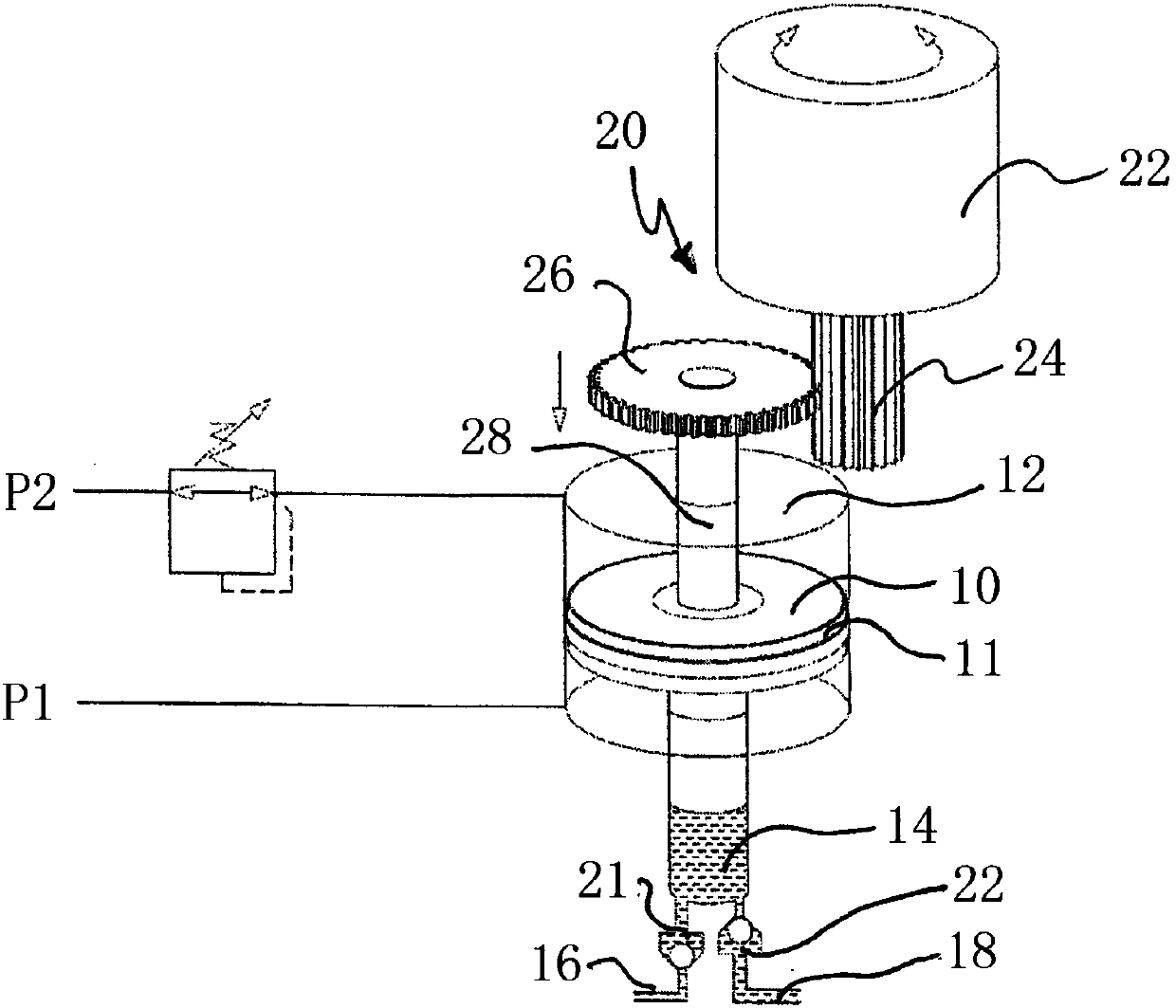
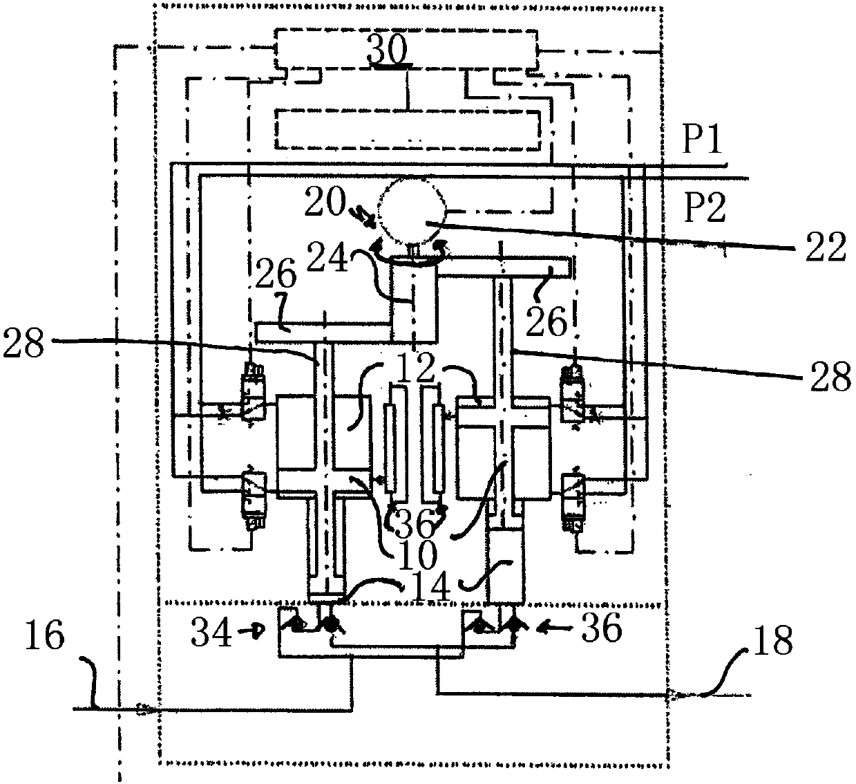
[0023] figure 1 A first embodiment of a pressure transducer for liquid media is shown, which comprises a piston 10 which can be moved back and forth in a linear movement along a longitudinal axis in a piston chamber 12 . The piston 10 has a first cross section in the piston chamber 12 which is larger than a second cross section of the piston 10 which extends in the medium chamber 14 . As a result, a pressure conversion in proportion to the piston surface is possible in a manner known per se.

[0024] The medium chamber 14 is provided with an inlet 16 and an outlet 18 , wherein in the inlet 16 and in the outlet 18 there are non-return valves 21 and 22 connected in opposite directions.

[0025] In order to simultaneously move the piston 10 back and forth in the piston chamber 12 and in the medium chamber 14 , a linear drive (not shown in detail) in the form of two pressure lines P1 and P2 is provided. The piston 10 can be moved back and forth along the longitudinal axis in a l...


PUM


Abstract

A pressure converter for liquid mediums is provided, comprising a piston which moves linearly along a longitudinal axis. The piston is driven to rotate by a rotation driving device.

Description

technical field [0001] The invention relates to a pressure transducer for a liquid medium of a dosing system. Background technique [0002] The non-contact application of liquids such as adhesives or paints is now an integral part of modern manufacturing processes. It prevents damage to the workpiece or devices on the workpiece during the process. Application of adhesion promoters or adhesives, priming of devices or potting of LEDs are just a few examples of these manufacturing processes. The application of the respective medium takes place in a non-contact manner by means of so-called injection valves. In this case, individual droplets or streams of the medium are “sprayed” or thrown onto the workpiece at a small distance from the metering valve. [0003] In the applications described above, very high repeat accuracy is required in most cases, for example in order to ensure that the line width of the applied adhesive remains constant or that the same amount of medium or ...

Claims


Application Information

Patent Timeline
Patent Type & Authority Applications(China)
IPC IPC(8): F15B5/00B05C11/10
CPCB05C11/10F15B5/00F15B3/00F15B15/088F15B15/1452B05C5/02B05C11/1002H01L33/48
Inventor M·路透
Owner MARCO SYSTEMANALYSE UND ENTWICKLUNG GMBH
Learn More