Pipeline inner wall detection system and method

A detection system and pipeline technology, applied in measuring devices, instruments, using wave/particle radiation, etc., can solve problems such as leakage of transmission materials, casualties, environmental pollution, etc.

Active Publication Date: 2021-03-09
LASER RES INST OF SHANDONG ACAD OF SCI
View PDF5 Cites 0 Cited by
  • Summary
  • Abstract
  • Description
  • Claims
  • Application Information

AI Technical Summary

Problems solved by technology

If the local thinning problem in the pipeline cannot be found and dealt with in time, it will cause serious consequences such as damage to equipment and pipelines, leakage of transported materials leading to combustion or explosion, environmental pollution, production shutdown, and casualties
At present, there is no better solution to realize the detection of the inner wall of the pipeline

Method used


Image

  • Pipeline inner wall detection system and method
  • Pipeline inner wall detection system and method
  • Pipeline inner wall detection system and method

Examples


no. 1 example

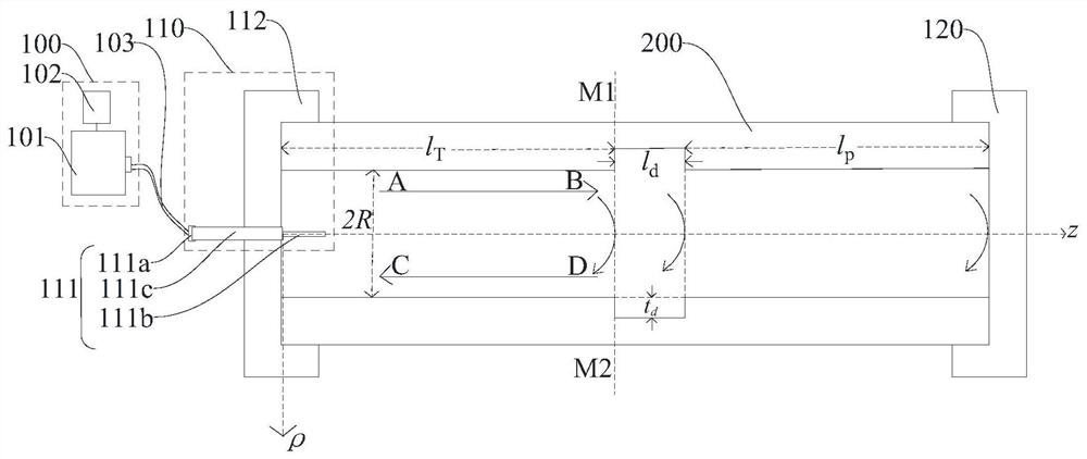
[0025] Please refer to figure 1 , this embodiment provides a detection system for the inner wall of a pipeline, which may include: a vector network analyzer device 100 and a coaxial feeding end cap device 110 . The input end of the coaxial feeding end cap device 110 is connected to the vector network analyzer device 100 , and the output end of the coaxial feeding end cap device 110 is used to connect to one end of the pipeline 200 to be tested.

[0026] The vector network analyzer device 100 is used to output microwaves and transmit the microwaves to the coaxial feeding end cover device 110 . Microwaves can be electromagnetic waves with a frequency of 300MHz to 300GHz, which is an abbreviation for a limited frequency band in radio waves.

[0027] The coaxial feeding end cover device 110 is used to propagate the received microwaves into the pipe to be tested 200, and when the inner wall of the pipe to be tested 200 is thinned, receive the microwaves through The echo signal re...

no. 2 example

[0101] see Figure 4 , the example of the present invention provides a method for detecting the inner wall of a pipeline, which is applied to the above-mentioned system, and the method may include:

[0102] Step S400: the vector network analyzer device outputs microwaves and transmits the microwaves to the coaxial feeding end cover device;

[0103] Step S410: The coaxial feeding end cover device propagates the received microwave into the pipeline to be tested, and when the inner wall of the pipeline to be tested is thinned, receives the microwave through the The echo signal reflected by the thinning part of the inner wall of the pipeline to be tested;

[0104] Step S420: the coaxial feed end cover device also transmits the received echo signal to the vector network analyzer device;

[0105] Step S430: The vector network analyzer device further processes the echo signal to obtain thinning information of the thinning part of the inner wall of the pipeline to be tested.

[010...


PUM

PropertyMeasurementUnit
electrical conductivityaaaaaaaaaa

Abstract

A pipeline inner wall detection system and method provided in embodiments of the present invention relate to the technical field of pipeline inner wall detection. The method comprises that the vector network analyzer device outputs microwaves and transmits the microwaves to the coaxial feeding end cover device; the coaxial feeding end cover device transmits the received microwaves into the pipeline to be tested, and when there is a When thinning, receive the echo signal reflected back by the thinning part of the inner wall of the pipe to be tested in the microwave; then the coaxial feeding end cover device will also transmit the received echo signal to the vector network analyzer device; the vector network The analyzer device also processes the echo signals to obtain thinning information at the thinning of the inner wall of the pipe under test. The wave impedance changes at the thinned part of the inner wall of the pipeline to be tested through microwaves, resulting in impedance mismatch, which causes the microwave to reflect at the thinned part in the time domain, and then processes the reflected echo signal to obtain the measured Thinning information at the thinning of the inner wall of the pipe. Improve detection accuracy.

Description

technical field [0001] The invention relates to the technical field of pipeline inner wall detection, in particular to a pipeline inner wall detection system and method. Background technique [0002] Pipeline transportation has a history of more than 150 years. It is widely used in industrial production and daily life. Oil and natural gas resources are mainly transported by buried pipelines (usually low alloy steel). During the operation of oil and gas pipelines, internal corrosion will lead to the thinning of the inner wall of the pipeline. The root cause is that the transport medium contains H2S, CO2 and other substances. First, H2S chemically reacts with carbon steel pipes, and hydrogen as one of the products can cause hydrogen damage to the pipes, while the other product, FeS, is usually a defective structure, which has poor adhesion to the steel surface and is prone to corrosion. It will fall off and act as a cathode to form an active micro-battery with the steel subst...

Claims


Application Information

Patent Timeline
Patent Type & Authority Patents(China)
IPC IPC(8): G01N22/02G01B15/02
CPCG01B15/02G01N22/02
Inventor 马健赵扬张振振贾中青巨阳周英丽陈建伟刘帅宋江峰郭锐王启武白雪南钢洋
Owner LASER RES INST OF SHANDONG ACAD OF SCI
Why Eureka
Try Eureka