Eureka AIR delivers breakthrough ideas for toughest innovation challenges, trusted by R&D personnel around the world.

High-precision geometric correction method for spatial image

A space image and geometric correction technology, applied in image enhancement, image analysis, image data processing, etc., can solve the problems of limitations, less research on hyperspectral image deformation, errors, etc., and achieve improved efficiency, wide application fields, and reliable accuracy Effect

Pending Publication Date: 2018-02-16
GUILIN UNIV OF AEROSPACE TECH
View PDF3 Cites 5 Cited by
  • Summary
  • Abstract
  • Description
  • Claims
  • Application Information

AI Technical Summary

Problems solved by technology

Polynomial models of different degrees and different numbers of control points are used to geometrically correct the photos, and the correction accuracy is compared. It is believed that the polynomial model has better fitting accuracy in relatively flat areas such as the observation datum or plane and ground. ; Some people use GPS data to geometrically correct the point pendulum sensor image, which can only achieve the effect of rough correction; there are relatively few studies on the deformation of the optimal hyperspectral image of the UAV platform; IMU / DGPS (inertial Although the method of Direct Georeferencing (DG) external azimuth element parameters of the combined system of measuring unit / differential GPS is superior to traditional aerial triangulation, its accuracy is still limited by the calibration errors of DGPS, IMU and other instruments

Method used


Image

  • High-precision geometric correction method for spatial image
  • High-precision geometric correction method for spatial image
  • High-precision geometric correction method for spatial image

Examples


Embodiment Construction

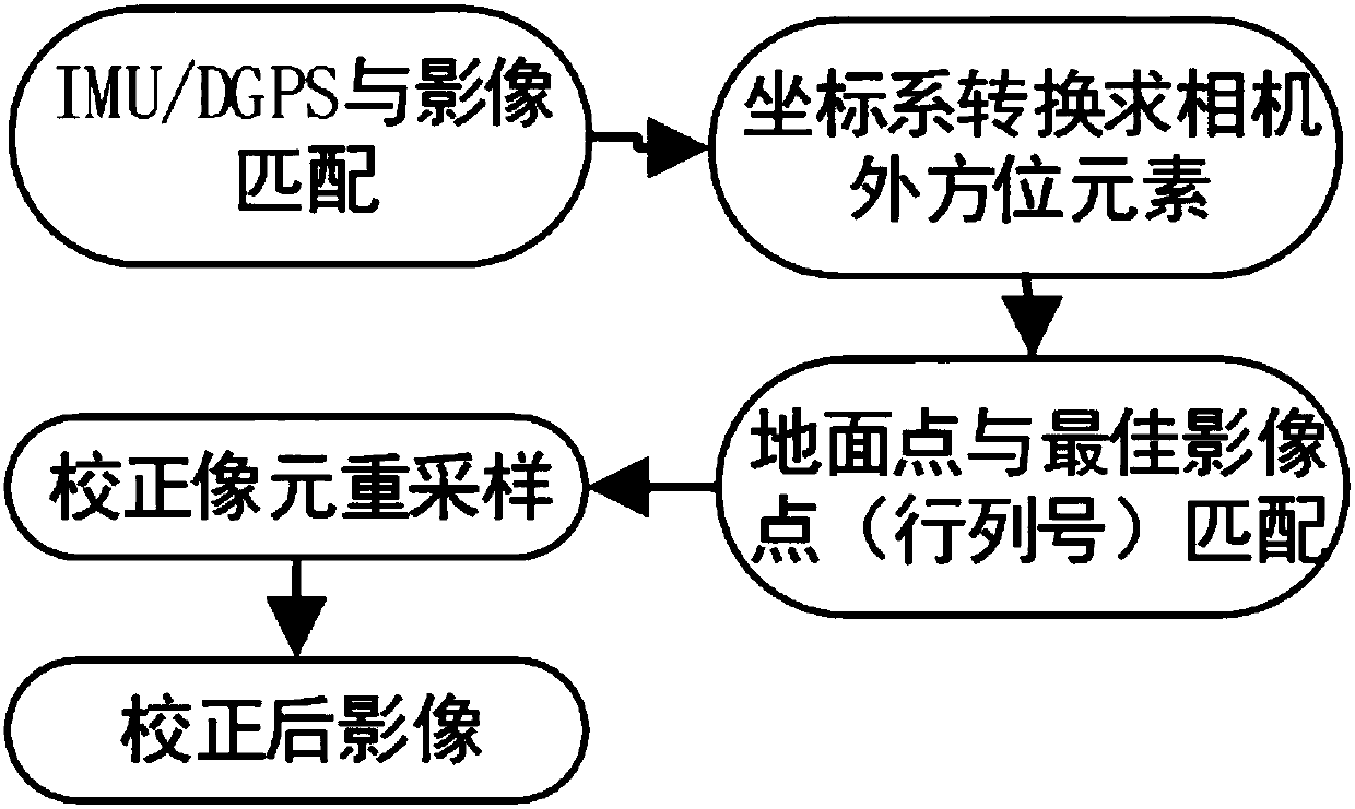
[0026] The specific implementation steps of the present invention will be described in detail below in combination with charts / formulas, etc. The method steps of the present invention are as figure 1 shown. A high-precision geometric correction method of a spatial image of the present invention comprises the following steps:

[0027] 1. Time matching processing of IMU / DGPS system acquisition data and spatial image data, including the following steps:

[0028] 1) Convert Beijing time and Greenwich mean time to achieve a unified time reference

[0029] The time read by the imaging payload is based on Beijing time, while the output of IMU / DGPS is GMT, so the conversion relationship between the two must be accurately determined before performing geometric processing. The conversion formula is

[0030] IMU / DGPS_time=(hour+16)×3600+minute×60+second (1)

[0031] In the formula, hour is the hour in the sampling time of the original image data; similarly, minute is minute; second i...


PUM


Abstract

The invention discloses a high-precision geometric correction method for a spatial image. The method comprises steps of: 1) matching the sampling time of data collected by a IMU / DGPS system with the sampling time of spatial image data, so that the sampling time of the data collected by the IMU / DGPS system is enabled to be matched with the sampling time of the spatial image data; 2) obtaining the element of exterior orientation of a camera through coordinate system conversion; 3) finding the pixel array number matching the ground coordinates of the spatial image data, i.e., the optimal scan array number according to the corresponding relationship between the spatial image data and the corresponding actual ground coordinates; 4) re-sampling the spatial image data according to the optimal scan array number obtained in the step 3) to obtain the corrected spatial image data. The method utilizes the data collected by the IMU / DGPS system to perform geometric correction on the spatial image, and can achieve high-precision image geometric correction for the ground motion measurement platform or air platform.

Description

technical field [0001] The invention relates to a high-precision geometric correction method for space images, and belongs to the technical fields of robot vision, surveying and remote sensing, and industrial measurement. Background technique [0002] For the geometric correction of images collected from multiple angles and multiple points in three-dimensional space, there are mainly approximation methods based on ground control points and correction methods based on position and attitude data. The two methods are different according to different requirements and actual conditions of specific implementation. [0003] There is a certain degree of research at home and abroad on geometric correction for different situations. Polynomial models of different degrees and different numbers of control points are used to geometrically correct the photos, and the correction accuracy is compared. It is believed that the polynomial model has better fitting accuracy in relatively flat are...

Claims


Application Information

Patent Timeline
IPC IPC(8): G06T5/00G06T3/40
CPCG06T3/4007G06T2207/30181G06T5/80
Inventor 赵海盟王强杨彬薛乐堂沈路宁
Owner GUILIN UNIV OF AEROSPACE TECH
Why Eureka
Eureka Blog
Learn More