Crystal oscillator power supply method and apparatus, and electronic device
A technology of crystal oscillator and power supply method, applied in power oscillators, electrical components, etc., can solve the problems of increasing power consumption and accelerating the start-up speed of crystal oscillators
- Summary
- Abstract
- Description
- Claims
- Application Information
AI Technical Summary
Problems solved by technology
Method used
Image
Examples
Embodiment 1
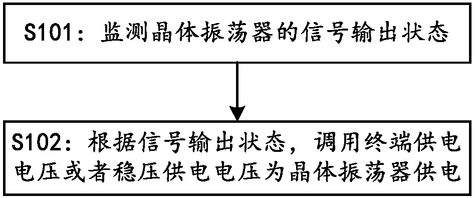
[0037] figure 1 For the flow chart of the crystal oscillator power supply method provided in Embodiment 1 of the present invention, please refer to figure 1 , the crystal oscillator power supply method provided in this embodiment includes the following steps:
[0038] S101: monitor the signal output state of the crystal oscillator;
[0039] S102: Call the terminal power supply voltage or the regulated power supply voltage to power the crystal oscillator according to the signal output state, and the regulated power supply voltage is lower than the terminal power supply voltage.
[0040] In some embodiments, step S102 includes:
[0041] When the signal output state is that the crystal oscillator has no output signal, use the terminal power supply voltage to power the crystal oscillator;
[0042] When the signal output state is the normal output signal of the crystal oscillator, use the regulated power supply voltage to power the crystal oscillator.
[0043] In some embodimen...
Embodiment 2
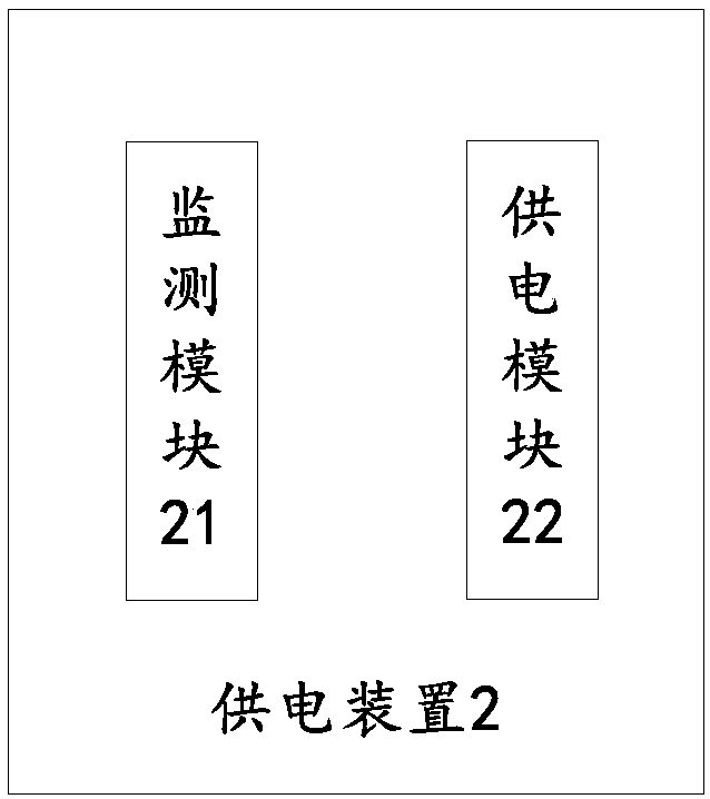
[0049] figure 2 For the structural diagram of the crystal oscillator power supply device provided in Embodiment 2 of the present invention, please refer to figure 2 , the crystal oscillator power supply device 2 provided in this embodiment includes:
[0050] The detection module 21 is used to monitor the signal output state of the crystal oscillator;
[0051] The power supply module 22 is configured to call the terminal power supply voltage or the regulated power supply voltage to power the crystal oscillator according to the signal output state, and the regulated power supply voltage is lower than the terminal power supply voltage.
[0052]In some embodiments, the power supply module 22 is specifically used to: when the signal output state is that the crystal oscillator has no output signal, use the terminal power supply voltage to supply power to the crystal oscillator; when the signal output state is that the crystal oscillator normally outputs a signal, use A regulated...
Embodiment 3
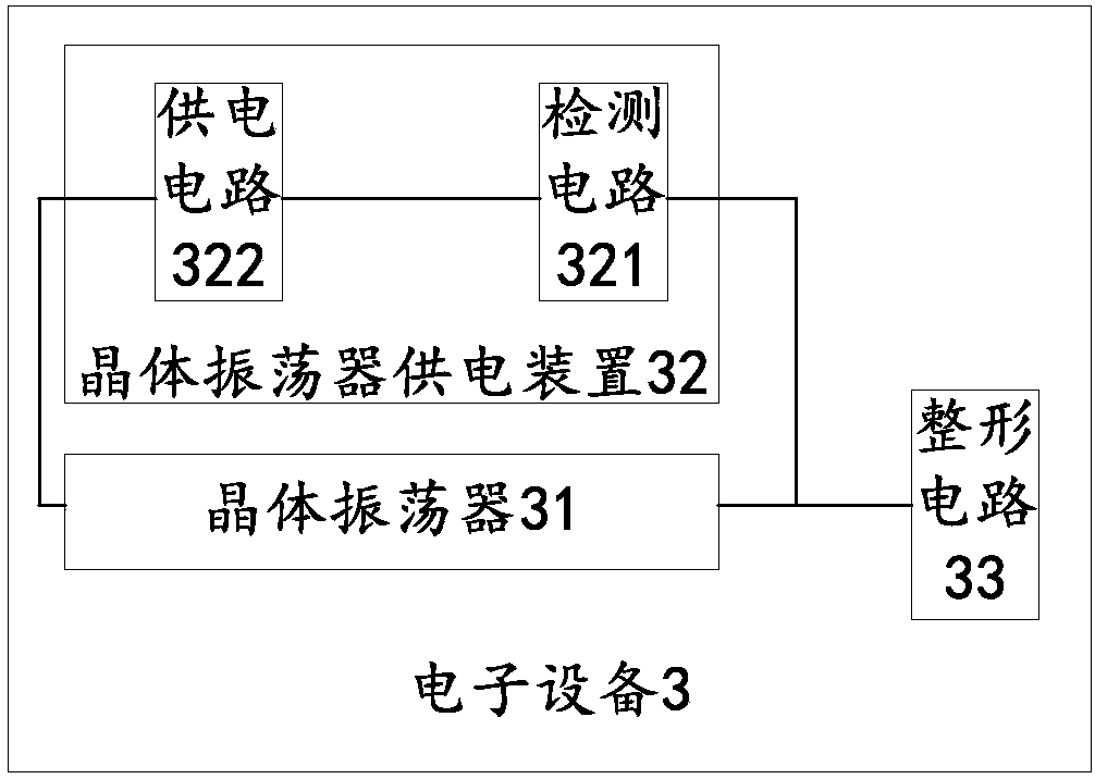
[0056] image 3 For the schematic structural diagram of the electronic device provided in Embodiment 3 of the present invention, please refer to image 3 The electronic device 3 provided in this embodiment includes: a crystal oscillator 31 for outputting an oscillating signal, and a crystal oscillator power supply device 32 for supplying power to the crystal oscillator, wherein the crystal oscillator power supply circuit 32 includes:
[0057] The detection circuit 321 is used to monitor the signal output state of the crystal oscillator, and output a level signal corresponding to the signal output state;
[0058] The power supply circuit 322 is used to call the terminal power supply voltage or the regulated power supply voltage to power the crystal oscillator according to the level signal, and the regulated power supply voltage is lower than the terminal power supply voltage.
[0059] In some embodiments, the power supply circuit 322 is specifically used to: when the level sig...
PUM
 Abstract
Description
Claims
Application Information
 - R&D
- Intellectual Property
- Life Sciences
- Materials
- Tech Scout
- Unparalleled Data Quality
- Higher Quality Content
- 60% Fewer Hallucinations
Browse by: Latest US Patents, China's latest patents, Technical Efficacy Thesaurus, Application Domain, Technology Topic, Popular Technical Reports.
© 2025 PatSnap. All rights reserved.Legal|Privacy policy|Modern Slavery Act Transparency Statement|Sitemap|About US| Contact US: help@patsnap.com


