Resonant transducer, method of producing the resonant transducer, and ultrasonic treatment tool including the resonant transducer

a technology of resonant transducers and ultrasonic treatment tools, which is applied in the field of resonant transducers, a method of producing resonant transducers, and an ultrasonic treatment tool including res, can solve the problems of increased vibration speed, increased treatment time, and insufficient vibration speed to enable ultrasonic treatment tools, etc., to achieve high vibration speed, the size of the treating part can be larger, and the effect of high vibration speed

Active Publication Date: 2015-05-05
FUJIFILM CORP
View PDF12 Cites 0 Cited by
  • Summary
  • Abstract
  • Description
  • Claims
  • Application Information

AI Technical Summary

Benefits of technology

[0018]According to the present invention, the internal stress of the piezoelectric film is a compressive stress equal to or more than 300 MPa, and hence a vibration speed equal to or more than 7.0 m / s can be obtained in the case of a resonant transducer having a rectangular configuration, leading to a wider range in design. In addition, in the case where the driving portion is provided in a portion to be inserted into a body, of a treatment tool, the drive voltage cannot be high, but according to the present invention, the vibration speed can be enhanced by increasing the drive voltage in a voltage range within which the treatment tool can work safely in the body.
[0020]According to the present invention, the vibrating plate has the surfaces supported only in the direction perpendicular to the vibration direction thereof, and hence the vibrating plate can be easily vibrated.
[0026]The resonant transducer according to the present invention can achieve a high vibration speed, and hence the vibration amplifying portion is not necessary, or the transformation ratio of the vibration amplifying portion can be smaller, so that the size of the treating part can be larger. Accordingly, the resonant transducer according to the present invention can be suitably applied to the ultrasonic treatment tool.

Problems solved by technology

Unfortunately, the vibration speed is not high enough to enable the ultrasonic treatment tool to perform incision and clotting, and hence the horn part that increases the vibration speed is necessary.
Accordingly, in consideration of actual use of the ultrasonic treatment tool in an endoscope, the size of the vibrating portion is limited to about 2 mm to 3 mm in diameter, and hence the treating part needs to be smaller than this size, resulting in an increase in treatment time.
In addition, the torque of the vibration is reduced in accordance with the transformation ratio, and hence the torque is unfavorably small.

Method used


Image

  • Resonant transducer, method of producing the resonant transducer, and ultrasonic treatment tool including the resonant transducer
  • Resonant transducer, method of producing the resonant transducer, and ultrasonic treatment tool including the resonant transducer
  • Resonant transducer, method of producing the resonant transducer, and ultrasonic treatment tool including the resonant transducer

Examples


examples

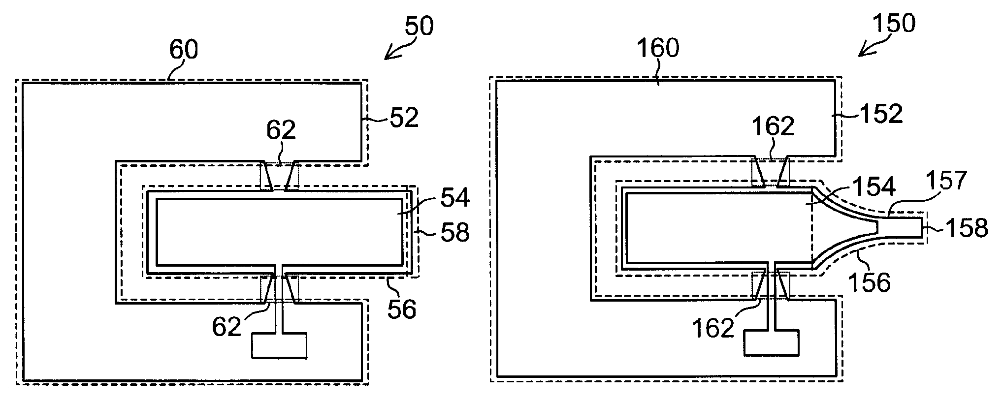
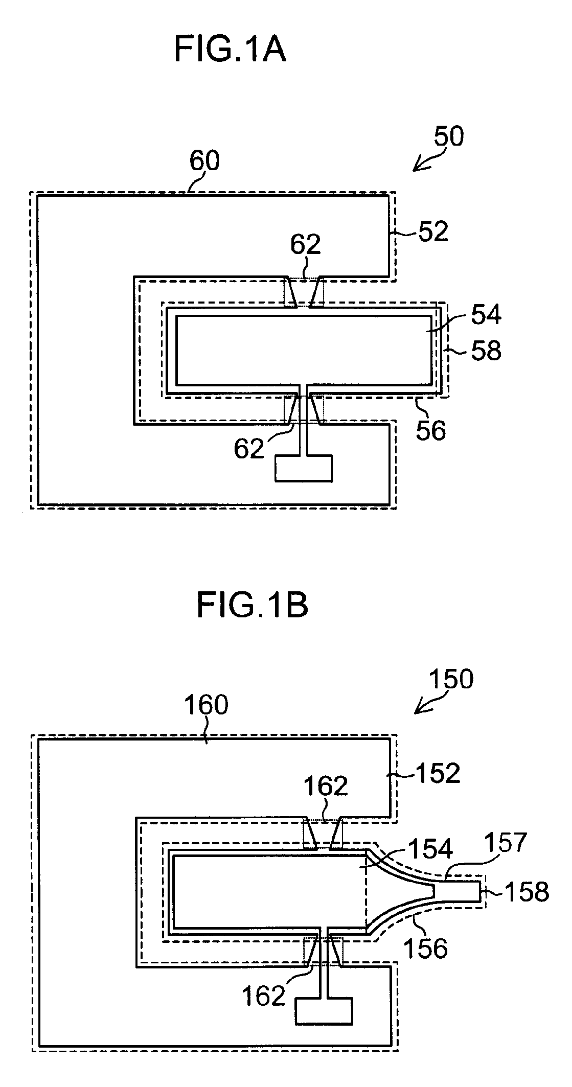
[0075]A resonant transducer having such a rectangular configuration as illustrated in FIG. 1A was produced using a substrate of a Ti alloy, that is, Ti-6Al-4V having a tensile strength of 800 MPa. The vibrating portion was fixed by the fixing portion to the supporting portion. The thickness of the substrate was 0.3 mm.

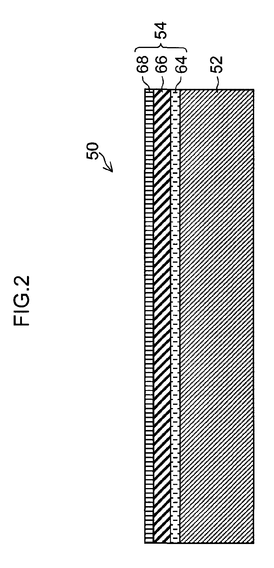
[0076]A first layer TiW having a thickness of 50 nm and a second layer Ir having a thickness of 150 nm were formed on the substrate by sputtering as the lower electrode. A lead zirconate titanate (PZT) film was formed on the lower electrode by sputtering under the respective conditions of a film forming temperature of 550° C. (Example 1), a film forming temperature of 600° C. (Example 2), and a film forming temperature of 650° C. (Example 3). The thickness of the piezoelectric film was 4 μm. Next, a first layer TiW having a thickness of 50 nm and a second layer Pt having a thickness of 150 nm were formed thereon by sputtering as the upper electrode. The film forming co...


PUM

PropertyMeasurementUnit
thicknessaaaaaaaaaa
thicknessaaaaaaaaaa
compressive stressaaaaaaaaaa

Abstract

A resonant transducer comprising:a vibration plate; anda piezoelectric element including a piezoelectric film and an upper electrode that are laminated on the vibration plate, whereina compressive stress is applied to the piezoelectric film.

Description

BACKGROUND OF THE INVENTION[0001]1. Field of the Invention[0002]The present invention relates to a resonant transducer, a method of producing the resonant transducer, and an ultrasonic treatment tool including the resonant transducer, and more particularly, to a resonant transducer that can achieve a high vibration speed, a method of producing the resonant transducer, and an ultrasonic treatment tool including the resonant transducer.[0003]2. Description of the Related Art[0004]In recent years, an incision site is required to be as small as possible in medical practice in terms of an early recovery after surgery and a reduction in burden on a patient, and endoscopic surgery is actively adopted as the solution. For the endoscopic surgery, various surgical tools have been developed, and the application range thereof is becoming increasingly wider. Under such a circumstance, an ultrasonic knife is expected as one of the tools for endoscopic surgery.[0005]With regard to ultrasonic treat...

Claims


Application Information

Patent Timeline
Patent Type & Authority Patents(United States)
IPC IPC(8): H01L41/09A61B17/00A61B17/22A61B17/32H01L41/08H01L41/25H01L41/316
CPCA61B17/2202A61B17/320036H01L41/081H01L41/316H01L41/25A61B2017/00526Y10T29/42H10N30/10513H10N30/03H10N30/076
Inventor HIRABAYASHI, YASUTOSHIFUJII, TAKAMICHI
Owner FUJIFILM CORP
Why Eureka
Try Eureka