Synchronous detection method and synchronous detection device

A technology for synchronous detection and detection results, applied in the field of communication, can solve the problem of low accuracy of synchronous detection, achieve the effect of improving the success rate and accuracy, and solving the compatibility problem

Active Publication Date: 2018-02-16
SHENZHEN RENERGY TECH
View PDF4 Cites 2 Cited by
  • Summary
  • Abstract
  • Description
  • Claims
  • Application Information

AI Technical Summary

Problems solved by technology

[0004] In view of this, the embodiment of the present invention provides a synchronous detection method and a synchronous detection device to solve the problem of low accuracy of synchronous detection in the prior art

Method used


Image

  • Synchronous detection method and synchronous detection device
  • Synchronous detection method and synchronous detection device
  • Synchronous detection method and synchronous detection device

Examples


Embodiment 1

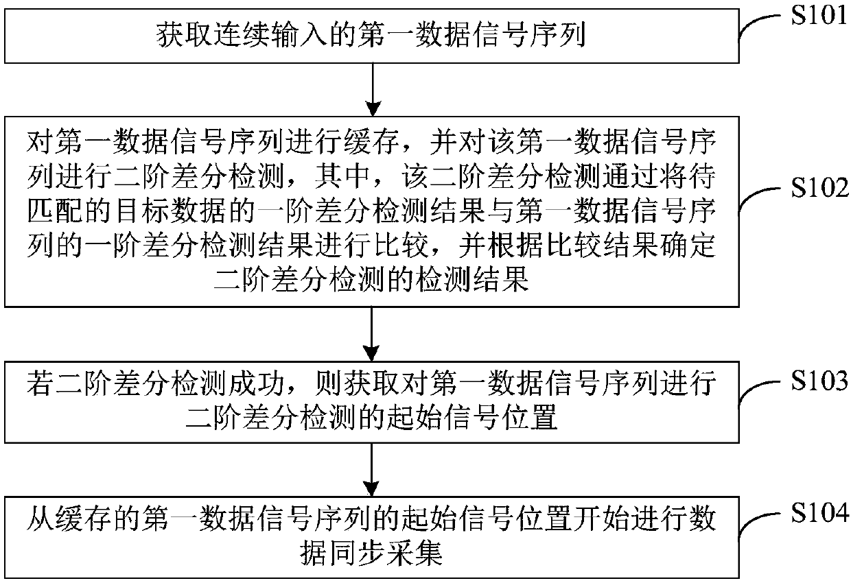
[0035] figure 1 It is a flowchart of a synchronous detection method provided in Embodiment 1 of the present invention. The execution subject of the embodiment of the present invention is a synchronous detection device, which may specifically be a hardware device including a synchronous detection device, etc. figure 1 An exemplary synchronous detection method may specifically include steps S101 to S104, which are described in detail as follows:

[0036] S101: Acquire a continuously input first data signal sequence.

[0037] Specifically, in the process of receiving wireless signals such as Bluetooth, the signal received from the antenna is amplified by a low noise amplifier (Low Noise Amplifier, LNA), and then enters an analog-to-digital converter (Analog-to-Digital Converter, ADC ) to complete the analog-to-digital conversion, after converting the analog signal into a digital signal, extract the I-way data and Q-way data of the digital signal, and perform automatic gain contr...

Embodiment 2

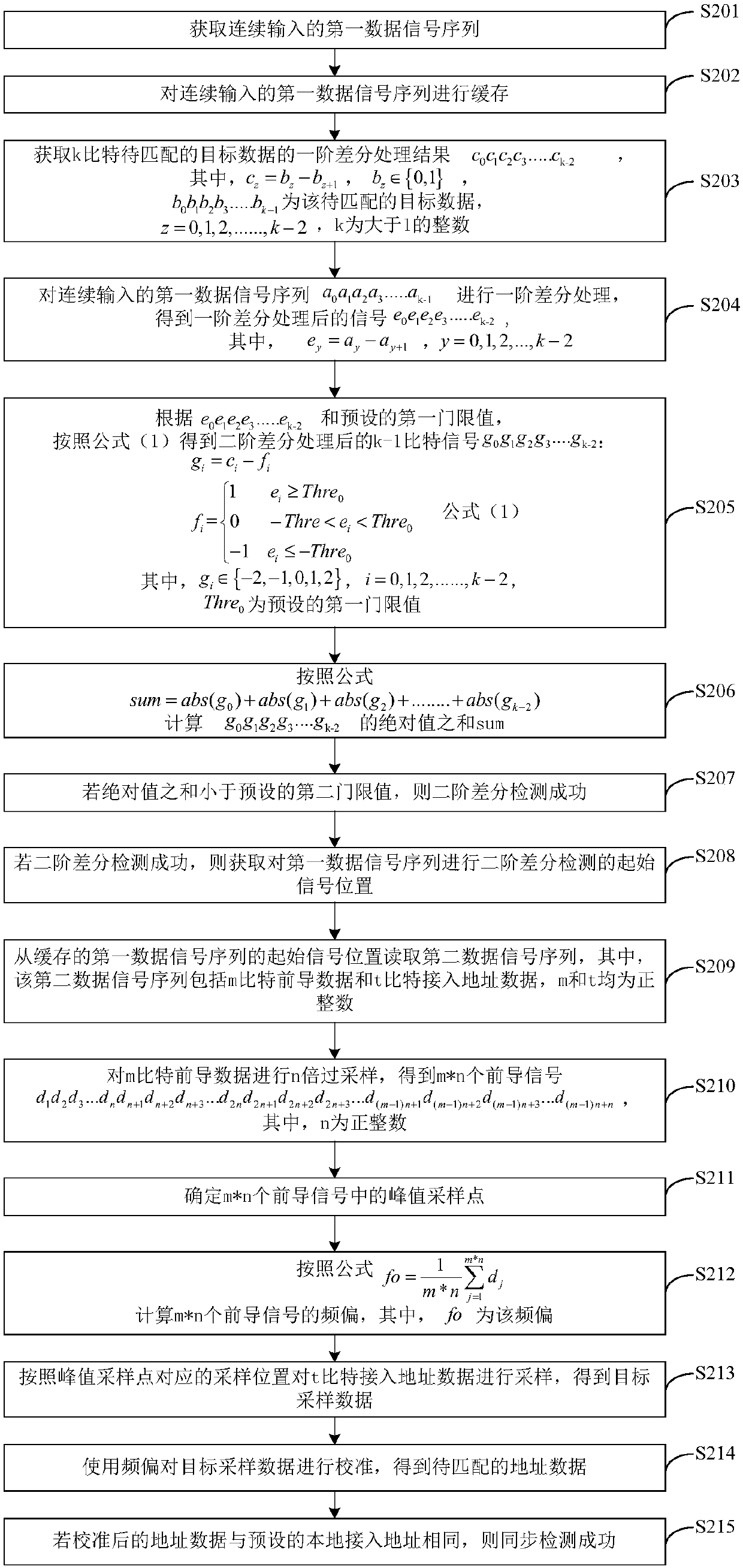
[0053] figure 2 It is a flow chart of a synchronous detection method provided in Embodiment 2 of the present invention. The execution subject of the embodiment of the present invention is a synchronous detection device, which may specifically be a hardware device including a synchronous detection device, etc. figure 2 An exemplary synchronous detection method may specifically include steps S201 to S215, which are described in detail as follows:

[0054] S201: Acquire continuously input first data signal sequences.

[0055] Specifically, in the process of receiving wireless signals such as Bluetooth, after the signal received from the antenna is amplified by the LNA, it enters the ADC to complete the analog-to-digital conversion, and after the analog signal is converted into a digital signal, the I channel of the digital signal is extracted. Data and Q-channel data, after performing digital front-end processing such as AGC and filter processing on the extracted I-channel dat...

Embodiment 3

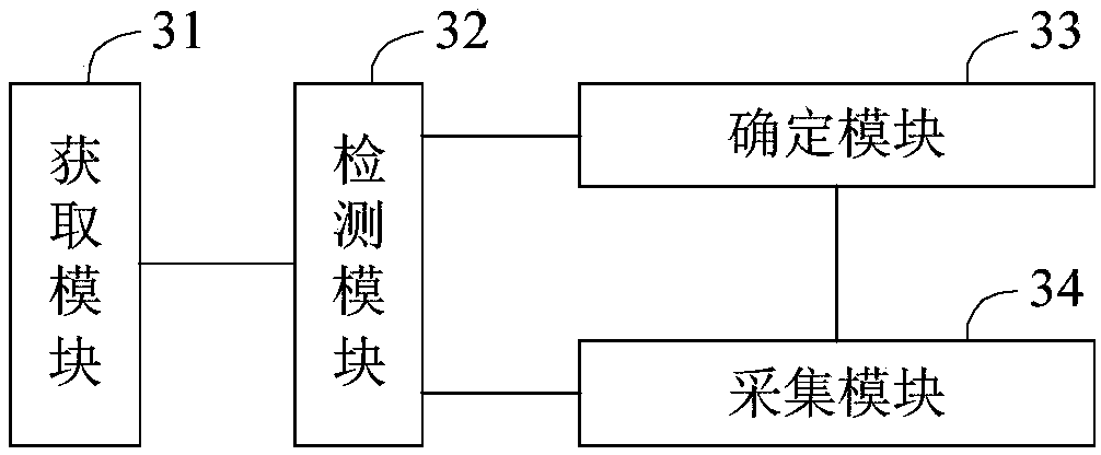
[0128] image 3 It is a schematic structural diagram of a synchronous detection device provided in Embodiment 3 of the present invention. For convenience of description, only the parts related to the embodiment of the present invention are shown. image 3 An exemplary device for synchronous detection may be the subject of execution of the method for synchronous detection provided in Embodiment 1 above. image 3 An exemplary synchronous detection device includes: a receiving module 31, a detection module 32, a determination module 33 and an acquisition module 34, and each functional module is described in detail as follows:

[0129] An acquisition module 31, configured to acquire the first data signal sequence input continuously;

[0130] The detection module 32 is configured to buffer the first data signal sequence, and perform a second-order differential detection on the first data signal sequence, wherein the second-order differential detection uses the first-order differen...


PUM


Abstract

The invention is applicable to the field of communication technology, and provides a synchronous detection method and a synchronous detection device. The method comprises the following steps: obtaining a continuously input first data signal sequence; caching the first data signal sequence, and performing second-order differential detection on the first data signal sequence; if the second-order differential detection is successful, obtaining a starting signal position of the second-order differential detection of the first data signal sequence; and starting synchronous data collection from thestarting signal position of the first data signal sequence. According to the technical scheme of the invention, the second-order differential detection is performed on the first data signal sequence to obtain an accurate reading position of the starting signal of the first data signal sequence, and accurate data collection is accomplished according to the reading position, thereby solving the compatibility problem of different signal amplitudes, and achieving accurate synchronous detection of wireless data, and greatly improving the success rate and accuracy of synchronous detection.

Description

technical field [0001] The invention belongs to the technical field of communication, and in particular relates to a method for synchronous detection and a synchronous detection device. Background technique [0002] In the process of wireless communication, especially Bluetooth low-power communication, when the receiving device receives wireless data, it needs to analyze the wireless data according to the data format defined by the wireless protocol standard. Since wireless data is transmitted through wireless signals, the signals have a certain frequency and Amplitude, the receiving device needs to detect the received wireless signal synchronously to determine the signal collection point that can accurately obtain the wireless data. [0003] Most of the traditional synchronous detection methods use the energy detection of the leading signal in the wireless signal, and determine the maximum energy value by comparing with the fixed energy threshold. However, since there is no...

Claims


Application Information

Patent Timeline
IPC IPC(8): H04W24/08H04W56/00
CPCH04W24/08H04W56/0035
Inventor 林旺东陈力刘凯
Owner SHENZHEN RENERGY TECH
Why Eureka
Try Eureka