Bonding capillary

A rivet and inclined surface technology, applied in the field of welding ribbing, can solve the problems of poor peeling, poor welding rib life, poor filament cut-off, etc.

Active Publication Date: 2018-02-16
TOTO LTD
View PDF8 Cites 8 Cited by
  • Summary
  • Abstract
  • Description
  • Claims
  • Application Information

AI Technical Summary

Problems solved by technology

At this time, the filament will be embedded in the thick plating layer, which may reduce the bondability between the filament and the lead wire
Also, after the second welding, the chopping property of the filament becomes worse
If the cuttability of the filament is deteriorated,

Method used


Image

  • Bonding capillary
  • Bonding capillary
  • Bonding capillary

Examples


Embodiment approach

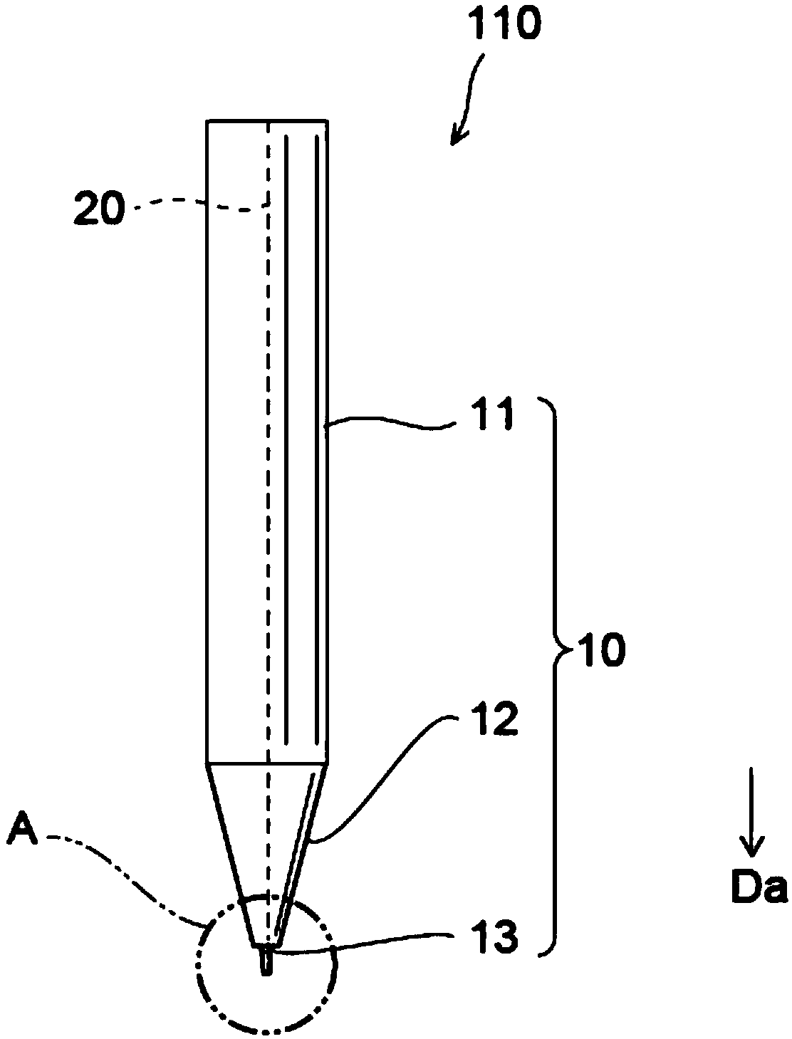
[0052] figure 1 It is a schematic diagram illustrating the welding capillary according to this embodiment.

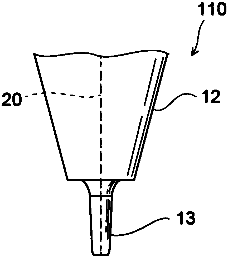
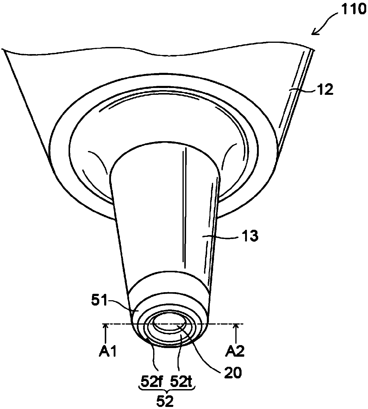
[0053] figure 2 It is a schematic enlarged view illustrating the tip shape of the welding capillary according to this embodiment.

[0054] figure 1 The welding capillary 110 as a whole is shown in . figure 2 is shown in the magnified figure 1 A diagram of area A is shown.

[0055] Such as figure 1 As shown, a welding capillary (hereinafter, sometimes referred to as “capillary”) 110 has a main body portion 10 . The main body portion 10 is a cylindrical member and has a through hole 20 . The through hole 20 is a through hole extending in the axial direction Da of the main body portion 10 . When using a riving knife, the thread passes through the through hole 20 .

[0056] The body part 10 is provided with: a cylindrical part 11 ; a conical part 12 provided on the front end side of the cylindrical part 11 ; and a bottle neck 13 provided on the front end side of ...


PUM

PropertyMeasurementUnit
Average heightaaaaaaaaaa

Abstract

Provided is a bonding capillary which is characterized in that: the bonding capillary is provided with a body comprising a through-hole into which a wire is inserted, a first pressing face which presses on the wire and has a first sloping face provided in the periphery of the through-hole and inclining along the extending direction of the through-hole, and a second pressing face which presses on the wire and has a tapered face provided between the first sloping face and the through-hole and a second sloping face provided between the tapered face and the first sloping face; and the root-mean-square gradient of the roughness curve element on the second sloping face is smaller than the root-mean-square gradient of the roughness curve element on the first sloping face.

Description

technical field [0001] Aspects of the present invention generally relate to a welding capillary. Background technique [0002] In the manufacturing process of a semiconductor device, wire bonding is performed to connect a semiconductor element and a lead frame with a bonding wire (hereinafter referred to as "wire"). In wire bonding, one end of a filament is bonded to an electrode pad of a semiconductor element with a bonding capillary (first bonding). Next the filament is pulled and bonded to the lead (second soldering). When joining filaments, ultrasonic waves are applied while pressing the filaments with a welding capillary. [0003] For example, in the second soldering, the main bonding portion (stitch bonding portion) between the filament and the lead wire, and the temporary bonding portion (tail wire bonding portion) between the filament and the lead wire are formed. After such a second bond, the filament extending from the tail bond is severed (cut). Thereafter, th...

Claims


Application Information

Patent Timeline
IPC IPC(8): H01L21/60
CPCH01L2224/45147H01L2224/78303H01L2224/78305H01L2924/00014H01L24/745H01L24/78H01L2224/78307
Inventor 冈总一郎大西惇平石塚祐司本村研一
Owner TOTO LTD
Why Eureka
Try Eureka