
Drill bits with replaceable inserts and bits

A drill and blade technology, used in cutting inserts, drilling/drilling equipment, drilling, etc., can solve problems such as breakage, damage to cutting edge strength, reduction, etc., to prevent breakage, improve cutting performance, and restrain deflection. Effect

Inactive Publication Date: 2017-07-14
MITSUBISHI MATERIALS CORP
View PDF2 Cites 0 Cited by
  • Summary
  • Abstract
  • Description
  • Claims
  • Application Information

AI Technical Summary

Problems solved by technology

In order to reduce this cutting resistance, for example, if a chip breaker is formed on the cutting edge and the rake angle of the cutting edge formed by the chip breaker is increased, the cutting edge becomes sharper and the resistance decreases. , but the cutting edge strength will be damaged
Therefore, when the cutting edge of the drill insert on the outer peripheral side cuts into the workpiece, the deflection of the drill is released, and the drill insert on the axial side instantly returns to its original position, and the cutting edge receives an impact load at this time. In particular, when viewed from the direction facing the above-mentioned square surface, damage may occur on the other end side of the cutting edge intersecting the axis at a relatively low speed in the peripheral direction due to the rotation of the drill body.

Method used


Image

  • Drill bits with replaceable inserts and bits
  • Drill bits with replaceable inserts and bits
  • Drill bits with replaceable inserts and bits

Examples


Embodiment Construction

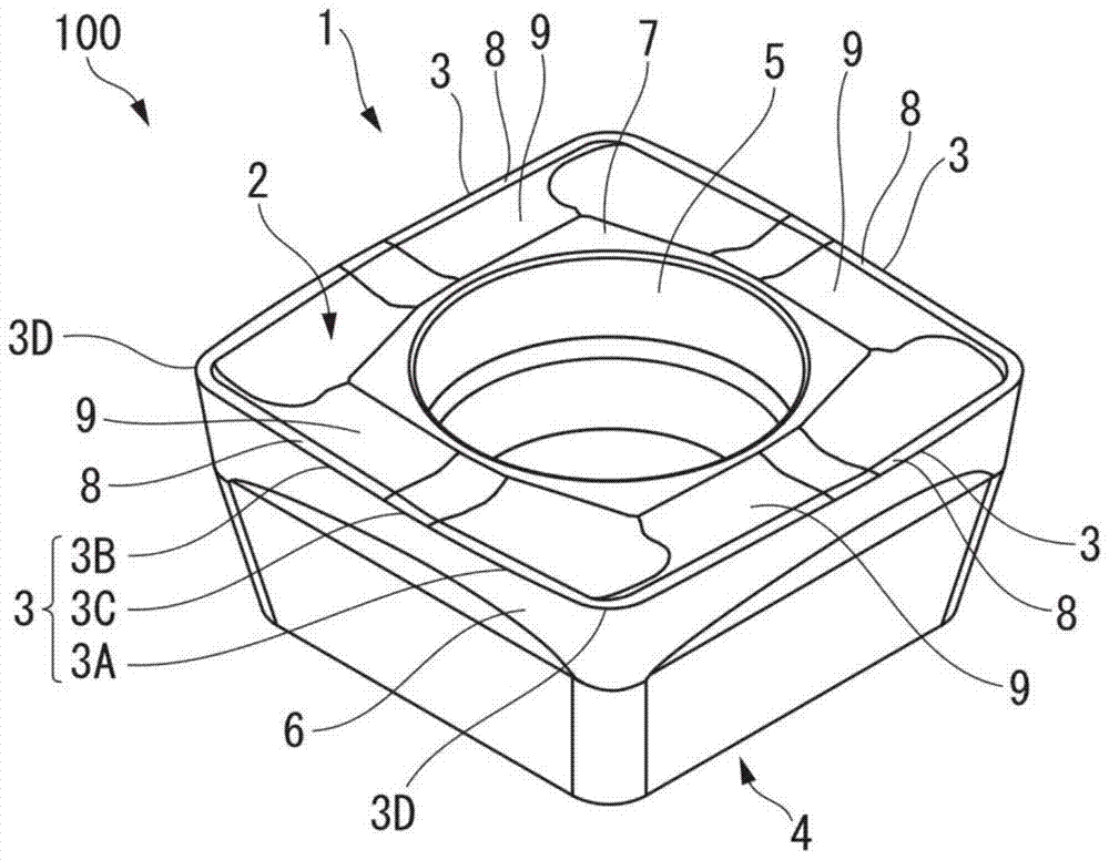
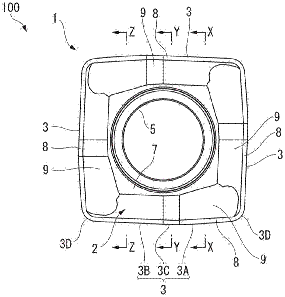
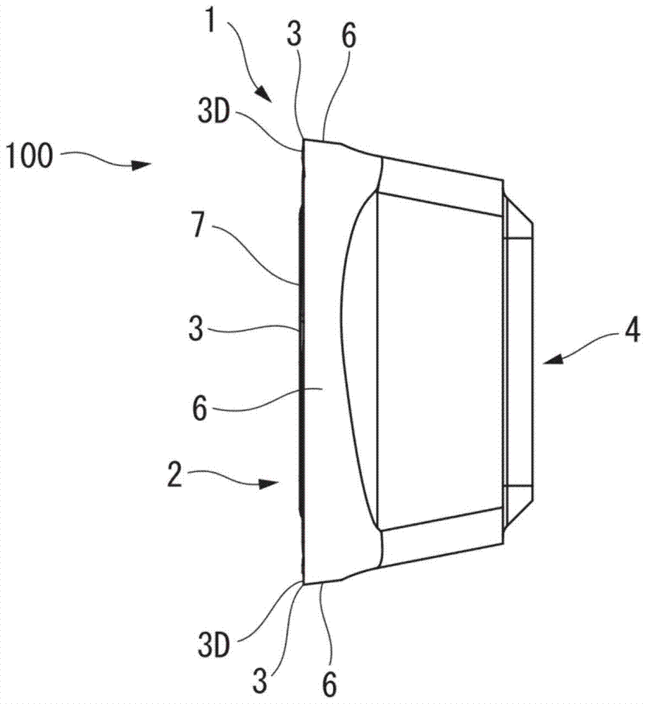
[0030] Figure 1 to Figure 9 An embodiment of the insert for a drill of the present invention is shown, Figure 10 to Figure 12 One embodiment of the replaceable bit drill 200 of the present invention to which the drill insert 100 is mounted is shown. In the drill insert 100 of this embodiment, the insert main body 1 is formed in a polygonal flat plate shape by a hard material such as cemented carbide, specifically, in this embodiment, it is formed in a substantially square flat plate shape. Each of the four edge portions is formed with a cutting edge 3 having the one square face as the rake face 2 .

[0031] And, another square surface of the insert main body 1 is the supporting surface 4, and the center of the supporting surface 4 is formed along the thickness direction of the insert main body 1 ( Figure 3 to Figure 6 The center is the left-right direction) through the installation hole 5 of the blade main body 1 . The blade main body 1 has a shape that is rotationally s...


PUM


Abstract

The insert for a drill according to the present invention is detachably installed on the axis (O) side and the outer peripheral side of the tip of the drill body (11) rotating around the axis (O). The edge portion of the polygonal surface in the direction of drill rotation is formed with cutting edges (3) facing toward the tip side of the drill body (11) and trajectories of rotation around the axis (O) when viewed from the direction of the axis (O). The cutting edge (3) is provided with a margin (8), and the margin angle of the margin (8) changes with the cutting edge (3) located on the outer peripheral side of the drill body (11) when it is installed on the drill body (11). One end (3A) of the cutting edge (3) gradually increases toward the negative angle side toward the other end (3B), and the land width of the land (8) increases from one end (3A) of the cutting edge (3) to the other end The (3B) side gradually increases.

Description

technical field [0001] The present invention relates to a drill insert detachably attached to a drill with a replaceable drill bit for drilling a material to be cut, such as stainless steel or mild steel, and a replaceable drill with the drill insert mounted thereon. [0002] This application claims priority based on Patent Application No. 2013-061393 for which it applied in Japan on March 25, 2013, and uses the content here. Background technique [0003] As such an insert for a drill, for example, Patent Document 1 proposes an insert having a substantially square plate-shaped insert body, a cutting edge is formed on a side edge of one square surface of the insert body, measured from the bottom surface of the insert body The height of the cutting edge varies along the length of the cutting edge. [0004] In addition, Patent Document 1 also describes a drill bit with a replaceable bit, wherein two such drill inserts are detachably mounted at intervals in the circumferential ...

Claims


Application Information

Patent Timeline
IPC IPC(8): B23B51/00
CPCB23B2200/3672Y10T407/1924Y10T408/905B23B51/00B23B2251/50
Inventor 松永光平川出保彦田中省吾佐藤隆广
Owner MITSUBISHI MATERIALS CORP
Learn More