
Electric actuator

A technology of electric actuators and electric motors, which is applied in the direction of electric components, transmission devices, electromechanical devices, etc., and can solve problems such as poor movement of electric actuators, abnormal noise, and fixing to the housing

Active Publication Date: 2018-02-16
DENSO CORP
View PDF5 Cites 0 Cited by
  • Summary
  • Abstract
  • Description
  • Claims
  • Application Information

AI Technical Summary

Problems solved by technology

[0009] Therefore, when assembling the cover to the case, the gap between the cover-side bearing and the output shaft and the gap between the case-side bearing and the output shaft cannot be managed.
Therefore, by assembling in a state where there are no gaps between the bearing on the cover side and the output shaft and between the bearing on the housing side and the output shaft, it is possible to fix the cover in a state where an excessive load is applied to the output shaft. to the shell
[0010] In the state where the cover side bearing is pressed against the output shaft with an excessive load and the case side bearing is pressed against the output shaft with an excessive load, when the output shaft rotates, there is a possibility that Abrasion and other damage to bearings, housing side bearings, and output shafts
Specifically, it may cause malfunction of the electric actuator and occurrence of abnormal noise

Method used


Image

  • Electric actuator
  • Electric actuator
  • Electric actuator

Examples


Embodiment approach 1

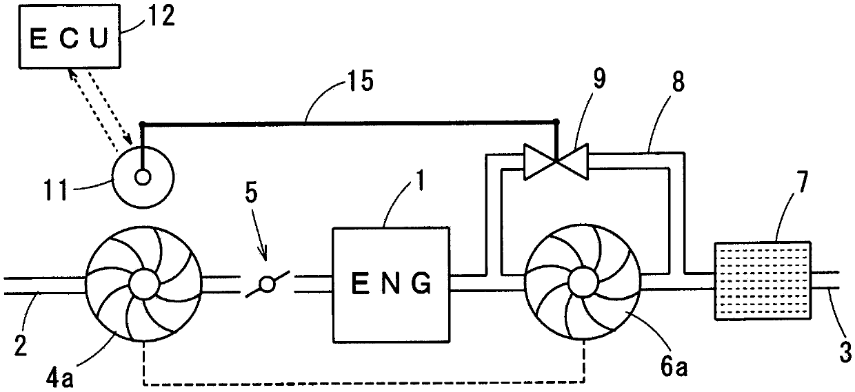
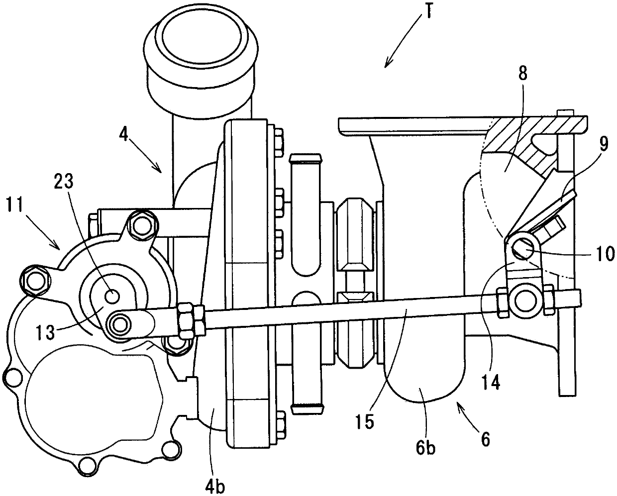
[0032] based on Figure 1 ~ Figure 12C Embodiment 1 will be described.

[0033] An engine 1 for traveling mounted on an automobile is provided with an intake passage 2 for guiding intake air into cylinders of the engine 1 , and an exhaust passage 3 for discharging exhaust gas generated in the cylinders to the atmosphere.

[0034] In the middle of the intake passage 2, an intake compressor 4 of the turbocharger T and a throttle valve 5 for adjusting the amount of intake air supplied to the engine 1 are provided.

[0035] In the middle of the exhaust passage 3, an exhaust turbine 6 of the turbocharger T and a catalyst 7 for purifying exhaust gas are provided. In addition, the catalyst 7 is a well-known three-way catalyst adopting a monolithic structure, and purifies harmful substances contained in the exhaust gas through oxidation and reduction by raising the temperature to the activation temperature.

[0036] The exhaust turbine 6 includes a turbine wheel (turbine wheel) 6a t...


PUM


Abstract

The positioning of a cover (24) with respect to a housing (20) is performed at two places, namely the place where "a first intermediate shaft (31) and a first recess (61) fit together" and the place where "a second intermediate shaft (32) and a second recess (62) fit together." As a result, the load of the cover (24) is not conveyed to an output shaft (23) via a cover-side bearing (34). Accordingly, when the cover (24) is in a state of being fixed to the housing (20), an excessive load is not generated between the cover-side bearing (34) and the output shaft (23), and between a housing-side bearing (33) and the output shaft (23).

Description

[0001] Cross-references to related applications [0002] This application is based on Japanese Patent Application No. 2015-123102 filed on June 18, 2015, the contents of which are disclosed in this specification. technical field [0003] The present invention relates to an electric actuator for rotating an output shaft. Background technique [0004] As an example of an electric actuator that rotates an output shaft, the technology disclosed in Patent Document 1 is known. [0005] The electric actuator in Patent Document 1 drives an output shaft by decelerating the rotational output generated by the electric motor with a parallel shaft type gear reducer. The gear reducer has an intermediate shaft parallel to the output shaft. The intermediate shaft is supported by the housing. [0006] On the other hand, one end of the output shaft is rotatably supported by a bearing arranged between the housing and the output shaft (hereinafter referred to as a housing-side bearing). [...

Claims


Application Information

Patent Timeline
Patent Type & Authority Applications(China)
IPC IPC(8): H02K7/116F16H1/06F16H57/021
CPCF16H57/021H02K7/116H02K5/04H02K5/225F16H57/032F02B37/186F16H57/031F16H2057/02034F16H2057/02082Y02T10/12F16H1/06H02K11/215F16H19/001F16K31/043
Inventor 河野尚明岛田广树山中哲尔柳田悦豪
Owner DENSO CORP
Learn More