Oil groove filter screen for cutting fluid used for machine tool

A filter and cutting fluid technology, applied in the direction of filtration separation, fixed filter element filter, separation method, etc., can solve the problems of inconvenient use, troublesome filter installation and disassembly, and no good solution, etc., to achieve good filtering effect , good practicability and simple structure

Pending Publication Date: 2018-02-23
平湖智铂自动化设备股份有限公司
View PDF3 Cites 1 Cited by
  • Summary
  • Abstract
  • Description
  • Claims
  • Application Information

AI Technical Summary

Problems solved by technology

[0008] Only for the filtration of chips, there is no good solution for the floating oil in the cutting fluid; and the filter in the cutting fluid filtering device is troublesome to assemble and disassemble, and it is inconvenient to use

Method used


Image

  • Oil groove filter screen for cutting fluid used for machine tool
  • Oil groove filter screen for cutting fluid used for machine tool

Examples


Embodiment

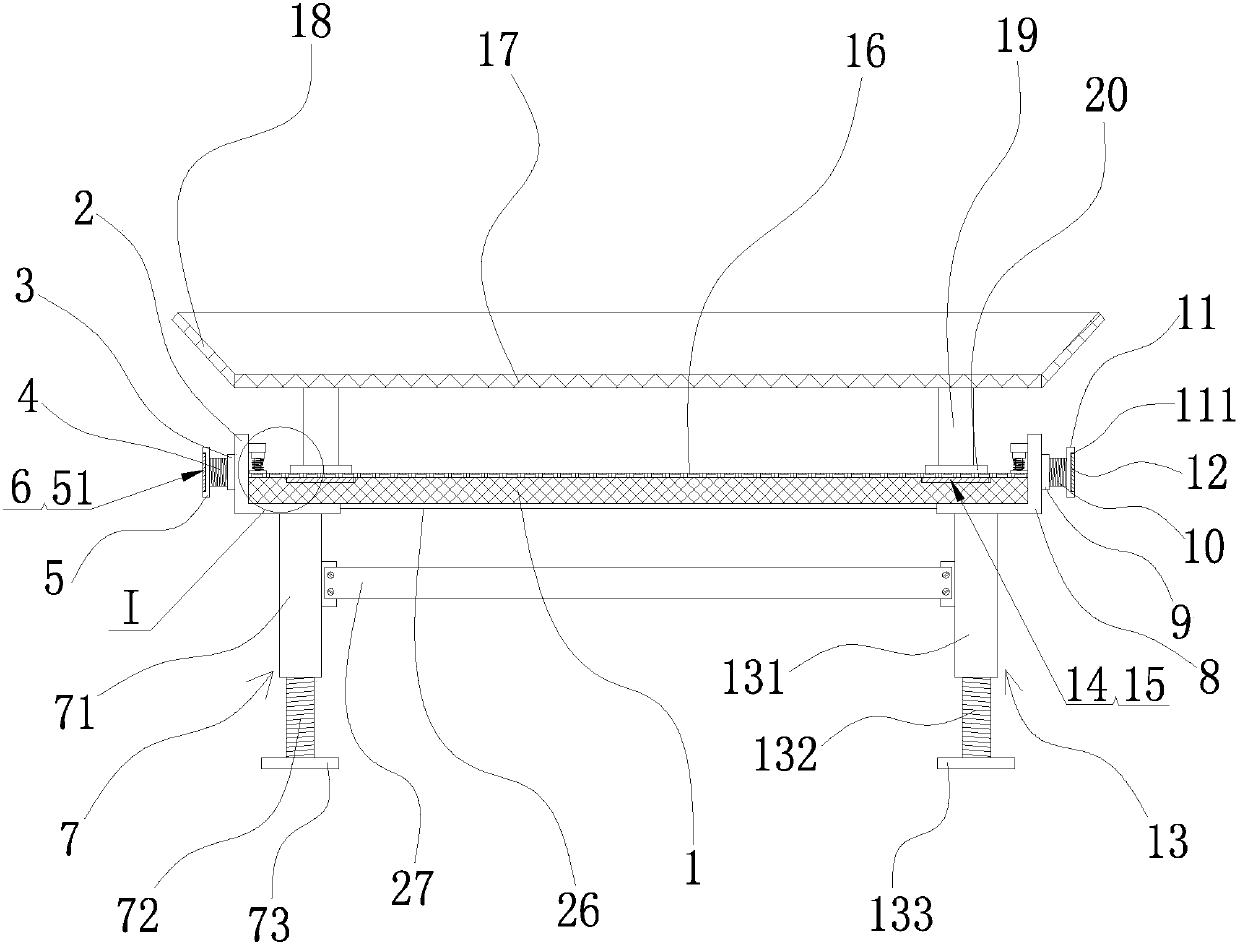
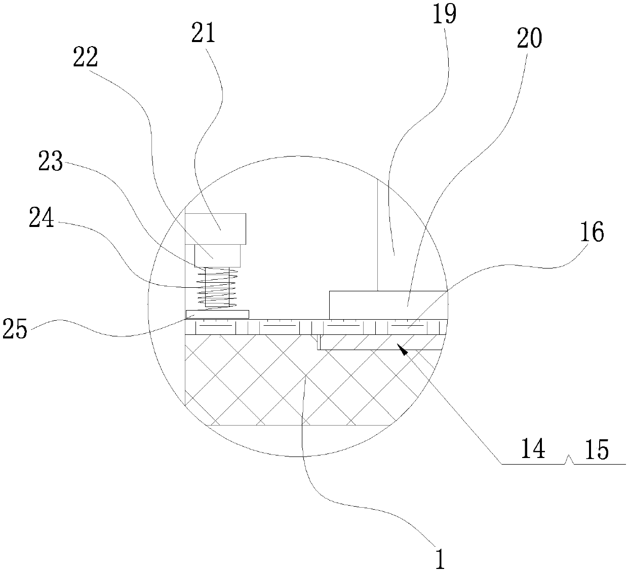
[0026] Example: such as figure 1 with figure 2 As shown, a cutting fluid oil tank filter screen for machine tools includes a filter screen body 1, a first positioning bracket 2 is welded on the left end of the filter screen body 1, and a first positioning bracket 2 is welded on the left end surface of the first positioning bracket 2. A positioning nut 3, the nut hole internal thread of the first positioning nut 3 is connected with a first adjusting screw 4, the left end of the first adjusting screw 4 is welded with a first positioning plate 5, the first positioning plate 5 is provided with a first storage groove 51 on the left end surface of the first storage groove 51, and a first magnet 6 is embedded in the first storage groove 51, and the first magnet 6 is glued to the inner wall surface of the first storage groove 51. connected and fixed; the lower end of the first positioning bracket 2 is provided with a left supporting foot 7; the right end of the filter body 1 is weld...


PUM


Abstract

The invention relates to an oil groove filter screen for a cutting fluid used for a machine tool. The oil groove filter screen comprises a filter screen body; the left end of the filter screen body iswelded with a first positioning support; the left end surface of the first positioning support is welded with a first set nut; the nut hole of the first set nut is in threaded connection with a firstadjusting screw; the left end of the first adjusting screw is welded with a first locating plate; a first object holding groove is arranged on the left end surface of the first locating plate; a first magnet is embedded into the first object holding groove; a left supporting leg is arranged at the lower end of the first locating plate; a plurality of third object holding grooves are arranged on the upper end surface of the filter screen body; each of the third object holding grooves is embedded with a third magnet; the upper end surface of the filter screen body is provided with a gauze filter layer; and the upper end surface of the gauze filter layer is detachably provided with a primary filter screen. With such a technical scheme, the oil groove filter screen is reasonable in layout, simple in structure, easy to assemble and disassemble, fixed, reliable, good in filtering effect and convenient to use.

Description

technical field [0001] The invention belongs to the technical field of machine tool equipment, and in particular relates to a cutting fluid oil tank filter screen for machine tools. Background technique [0002] During mechanical processing, it is often necessary to cool the cutting tool and workpiece with cutting fluid. [0003] It will bring the chips generated during processing to the cooling water tank, which will not only easily cause damage to the water pump, flushing pump, pipeline and water spray in the water tank [0004] The nozzle is blocked, which affects the cooling effect, and the cutting fluid mixed with chips is easy to cause secondary cutting on the workpiece, which affects the surface of the workpiece. [0005] Surface processing effect. In addition, during the lubricating process of the machine tool, the lubricating oil will also drip into the cutting fluid. [0006] In addition, it is easy to cause the cutting fluid to deteriorate and thicken, thereby ...

Claims


Application Information

Patent Timeline
IPC IPC(8): B01D29/56B01D29/03B01D29/05B01D29/96C10M175/00
CPCB01D29/03B01D29/05B01D29/56B01D29/96C10M175/0058
Inventor 李健
Owner 平湖智铂自动化设备股份有限公司
Why Eureka
Try Eureka