Copper bar cutting-off machine with automatic collecting mechanism

A technology of cutting machine and cutting mechanism, which is applied to the feeding device, positioning device, storage device, etc., can solve the problems of small adjustment range of cutting length, damage and deformation of copper rods, and difficult to move, so as to avoid scatter and improve the The effect of production efficiency

Inactive Publication Date: 2018-02-23
鹤山市鹤城镇合顺达金属制品厂
View PDF0 Cites 0 Cited by
  • Summary
  • Abstract
  • Description
  • Claims
  • Application Information

AI Technical Summary

Problems solved by technology

However, there are many differences in the cutting of copper rods for cutting machines specially used for steel bars.
[0003] Due to the high toughness and strength of the steel bars, the steel bars cut by the steel bar cutting machine generally fall directly from the cutting edge to the ground, which also causes confusion in the placement of the steel bars and is not easy to move; at the same time, because the steel bars are generally used in the construction industry, their length The size change is small, so the adjustment range of the cutting length is generally very small
The above characteristics are not suitable for cutting copper rods, because the copper rods will be damaged and deformed by violent impact, and a production line often needs to produce copper rods of different types and with a large length span, and the cut copper rods need to be cut. Frequent transfer to the next assembly line operation requires that the cut copper rods must be placed neatly and cannot be stacked in disorder. These requirements cannot be met by the existing steel bar cutting machines

Method used


Image

  • Copper bar cutting-off machine with automatic collecting mechanism
  • Copper bar cutting-off machine with automatic collecting mechanism

Examples


Embodiment Construction

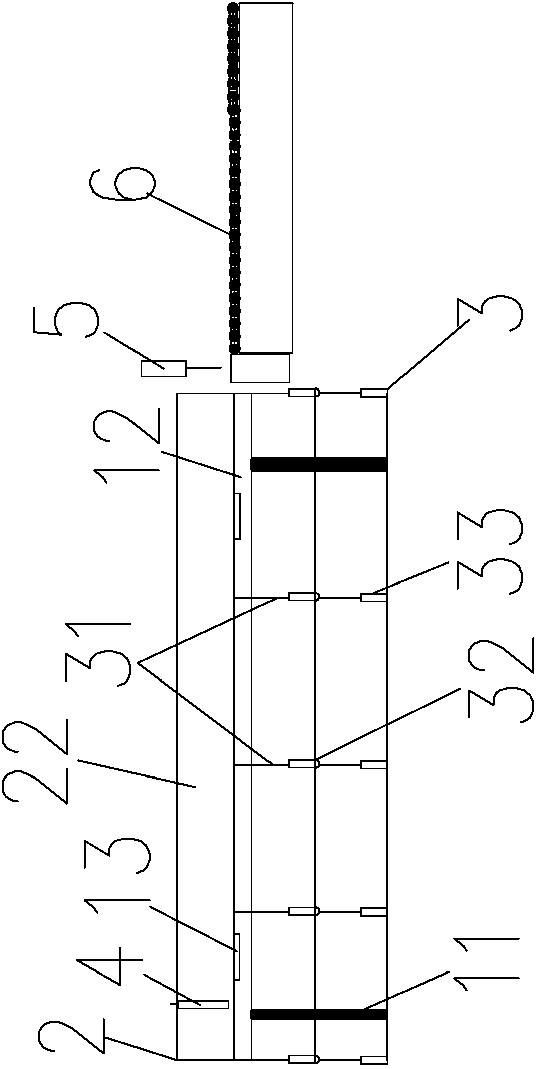
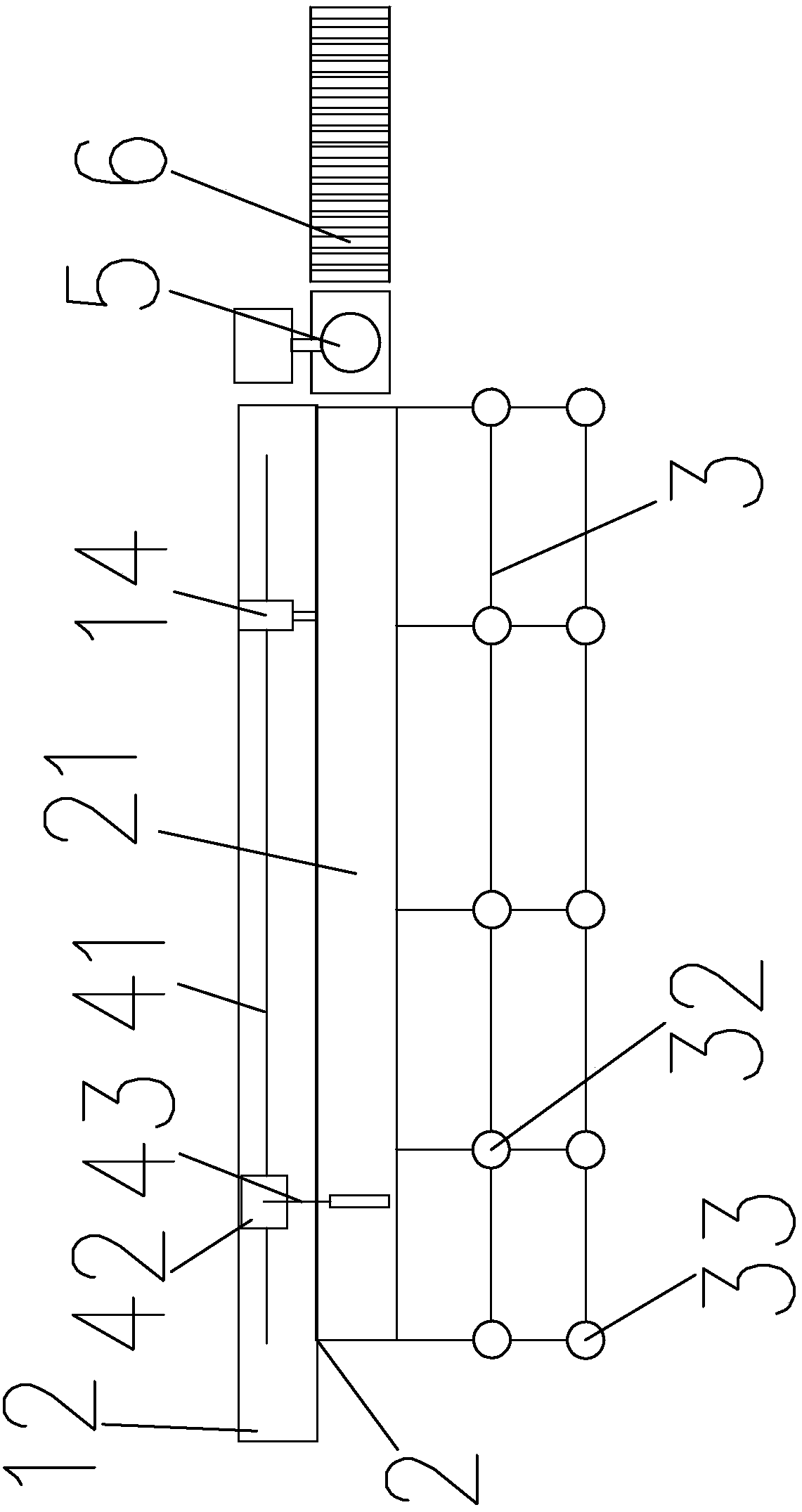
[0017] refer to figure 1 and figure 2 , a kind of copper rod cutting machine with automatic collecting mechanism of the present invention, comprises control system, air cylinder 14, conveyer belt 6, cutting mechanism 5, long table 1 and the collecting frame 3 that is arranged on the side of long table 1, described cutting Mechanism 5 is a high-speed punching machine, and the high-speed punching machine is provided with a sharp punching head, which can realize precise cutting of copper rods. The long table 1 includes four supporting legs 11 and a rectangular table top 12, the table top 12 is provided with a right-angled long groove 2 parallel to the rectangular table top 12, and the right-angled long groove 2 includes a vertical surface 22 and a horizontal surface 21, the vertical surface 22 and the horizontal surface 21 are welded at 90°, the horizontal surface 21 of the right-angled long groove 2 is wider than the vertical surface 22, and the outside of the right-angled lon...


PUM


Abstract

The invention discloses a copper rod cutting machine with an automatic collecting mechanism, which includes a control system, a cylinder, a conveyor belt, a cutting mechanism, a long table and a collecting frame arranged on the side of the long table, and the long table includes four supporting legs frame and a rectangular table top, the table top is provided with a right-angle long groove, the outer side of the right-angle long groove is rotatably arranged on the edge of the table top through a hinge, and the two ends of the cylinder are respectively connected to the table top and the outside of the right-angle long groove, so The right-angle slot is driven by the cylinder to rotate around the hinge axis, and a vertical limit baffle is arranged inside the right-angle slot. In the present invention, each cut copper rod is neatly stacked layer by layer on the collecting rack, which avoids the disadvantage of being scattered, and through the position of the limit block on the right-angle strip, the long-term The adjustment of the cutting length of the span is adapted to the characteristics of the copper rod processing industry and is conducive to improving production efficiency.

Description

technical field [0001] The invention relates to the technical field of metal rod cutting machines, in particular to a copper rod cutting machine with an automatic material collecting mechanism. Background technique [0002] In the production and processing of copper rods and wires, it is necessary to put the hot copper water obtained from the furnace into the mold for molding. First, a very long copper rod is obtained. In order to enter the next step of finishing, the copper rod must be cut off. , the cutting of the copper rod will use the corresponding cutting equipment. Due to the early appearance of the steel bar cutting machine and the large sales volume, the existing copper bar cutting machine is generally used to directly use the steel bar cutting machine to carry out the cutting process of the copper bar. However, there are many differences in the cutting of copper rods among cutting machines specially used for steel bars. [0003] Due to the high toughness and stre...

Claims


Application Information

Patent Timeline
IPC IPC(8): B21D28/02B21D43/12B21D45/02B21C51/00
CPCB21D28/02B21C51/00B21D28/002B21D43/006B21D43/12B21D45/02
Inventor 黄杰豪
Owner 鹤山市鹤城镇合顺达金属制品厂
Why Eureka
Try Eureka