
Wire stranding device of welding wire stranding machine and welding wire stranding machine

A technology of stranding machine and welding wire, which is applied in the direction of welding equipment, welding medium, welding/cutting medium/material, etc., can solve the problem that the size of the welding wire reel is restricted by the inner space of the twisted wire drum, and achieve compact structure, reduce downtime, The effect of small radial vibration

Active Publication Date: 2020-04-10
江苏科融新材料有限公司
View PDF8 Cites 0 Cited by
  • Summary
  • Abstract
  • Description
  • Claims
  • Application Information

AI Technical Summary

Problems solved by technology

[0009] Therefore, the technical problem to be solved by the present invention is to overcome the defect that the size of the wire reel of the wire stranding device of the prior art is restricted by the inner space of the wire reel, thereby providing a wire reel whose size is not limited by the size of the wire reel. Wire stranding device and welding wire stranding machine of welding wire stranding machine limited by cylinder space

Method used


Image

  • Wire stranding device of welding wire stranding machine and welding wire stranding machine
  • Wire stranding device of welding wire stranding machine and welding wire stranding machine
  • Wire stranding device of welding wire stranding machine and welding wire stranding machine

Examples


Embodiment 1

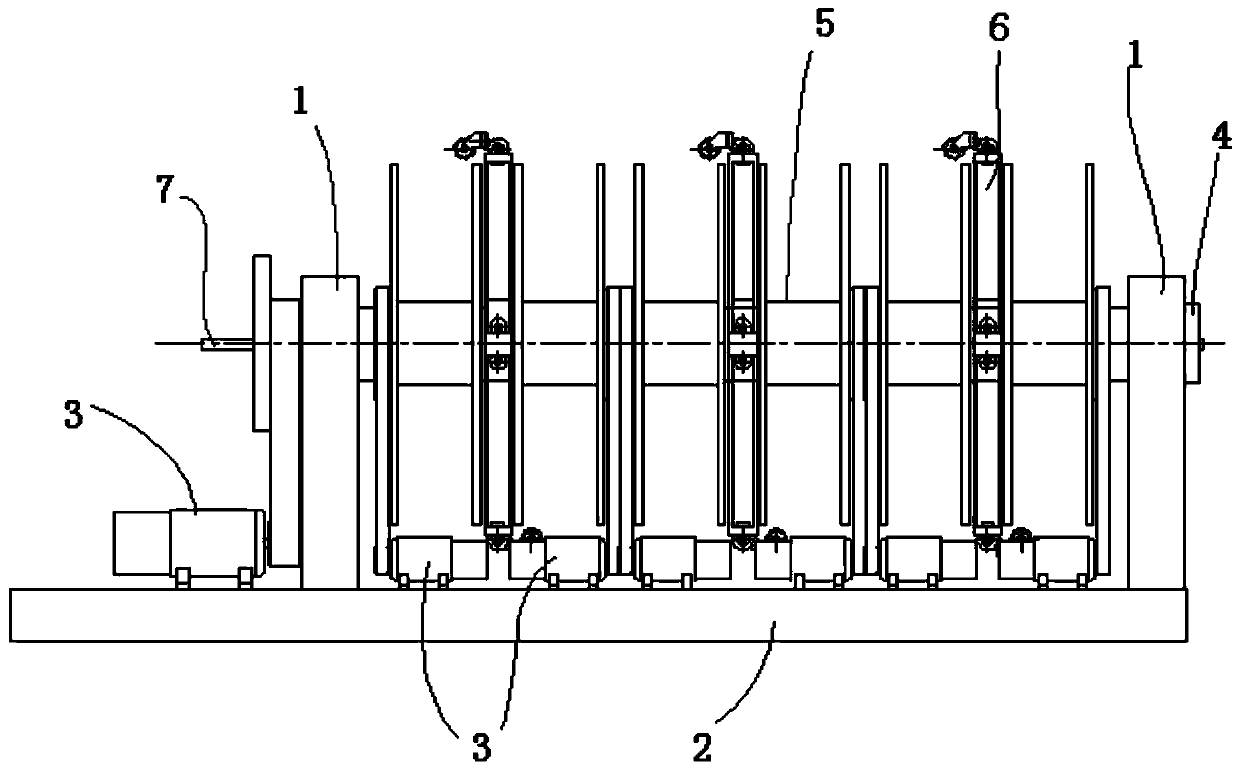
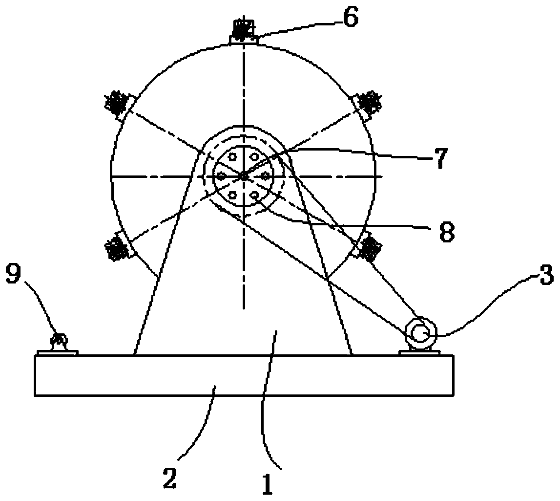
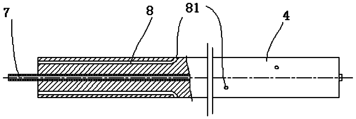
[0056] like Figure 1-2 A specific embodiment of the wire stranding device of the shown welding wire stranding machine includes a stranding cylinder 4, which is rotatably arranged on the support 1; a plurality of welding wire reels 5, including a central welding wire reel and peripheral welding wire The wire reel, the peripheral welding wire reel is pivotably sleeved on the outside of the said wire reel 4; the wire reel is arranged in the said reel 4, including the peripheral welding wire reel 8 and the central welding wire reel Pipe 7; a wire taking device, which guides the welding wire on the wire reel 5 into the corresponding wire feeding tube; a driving device, which drives the wire twisting drum 4 and the wire reel 5 to rotate respectively. Because the peripheral welding wire reel is pivotably sleeved on the outside of the wire reel 4, the diameter of the wire reel 5 is not restricted by the space of the wire reel 4, so the diameter of the wire reel 5 can be increased, an...

Embodiment 2

[0067] A welding wire stranding machine, comprising the stranding device described in the above-mentioned embodiments, a wire leveling device, a stress relief straightening device, and a wire receiving device are arranged at the outlet end of the stranding cylinder, and the welding wire stranding machine welding wire The size of the reel is not restricted by the space of the wire reel, the weight of the welding wire loaded on the wire reel is relatively large, and the production efficiency is high.


PUM


Abstract

The invention provides a wire twisting device of a welding wire twisting machine and the welding wire twisting machine. The wire twisting device comprises a wire twisting cylinder, a plurality of welding wire reels, wire winding tubes, a wire taking device and a driving device, wherein the wire twisting cylinder is rotatably arranged on a bracket; at least peripheral welding wire reels pivotally sleeve the outer side of the wire twisting cylinder; the wire winding tubes are arranged in the wire twisting cylinder, and comprise peripheral welding wire winding tubes and a central welding wire winding tube; the wire taking device is used for guiding welding wires on the welding wire reels into the corresponding wire winding tubes; and the driving device is used for driving both the wire twisting cylinder and the welding wire reels to rotate. As the peripheral welding wire reels are arranged on the outer side of the wire twisting cylinder, the diameters of the welding wire reels are not limited by the space of the wire twisting cylinder and can be increased, the welding wires loaded on the welding wire reels are relatively heavy, the idle hour caused by the replacement of the welding wire reels can be greatly shortened, and the production efficiency can be greatly improved.

Description

technical field [0001] The invention relates to the technical field of welding wire processing equipment, in particular to a wire stranding device of a welding wire stranding machine and a welding wire stranding machine. Background technique [0002] The cable-type welding wire is composed of a central welding wire and a coiled welding wire surrounding the central welding wire. Usually, a central welding wire and six coiled welding wires with a diameter equal to the central welding wire are stranded. Because the cable-type welding wire can greatly improve automatic welding and semi-automatic welding The welding productivity of welding is more and more concerned by the welding industry. [0003] Chinese patent document CN201824063U discloses a high-speed welding wire stranding machine, including a wire stranding device, a wire leveling device, a stress relief straightening device, and a wire receiving device for stranding welding wire, wherein the stranding device is mainly c...

Claims


Application Information

Patent Timeline
Patent Type & Authority Patents(China)
IPC IPC(8): B23K35/40
CPCB23K35/40
Inventor 时振王占梅魏宏兵
Owner 江苏科融新材料有限公司
Learn More