An on-board vehicle intelligent oil change cleaning maintenance system suitable for appointment service

A technology for on-board vehicles and maintenance systems, applied in the field of intelligent oil change and cleaning maintenance systems for on-board vehicles, which can solve the problems of long oil change time and long waiting time for owners, and achieve the effects of reducing the impact of weather, simple structure, and short time

Active Publication Date: 2019-08-16
奥吉星(山东)润滑油有限公司
View PDF2 Cites 0 Cited by
  • Summary
  • Abstract
  • Description
  • Claims
  • Application Information

AI Technical Summary

Problems solved by technology

At the maintenance point, it takes a long time for the vehicle to change the oil, and the owner has to wait for a long time

Method used


Image

  • An on-board vehicle intelligent oil change cleaning maintenance system suitable for appointment service
  • An on-board vehicle intelligent oil change cleaning maintenance system suitable for appointment service
  • An on-board vehicle intelligent oil change cleaning maintenance system suitable for appointment service

Examples


Embodiment 1

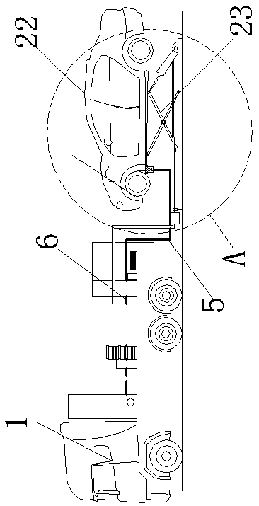
[0045] Example 1. Such as Figure 1-8 As shown, an on-board vehicle intelligent oil change, cleaning and maintenance system suitable for scheduled service is installed on the vehicle body 1, and the system includes an oil storage device, a lubricating oil mechanism, and a control device.

[0046] The oil storage device includes a recovery oil tank 2, a new oil tank 3, and a cleaning oil tank 11; the electromagnetic connecting valve 4 is provided with three oil inlets 41 and an oil outlet 42, and each oil inlet of the electromagnetic connecting valve 4 41. An electromagnetic valve is provided on the oil outlet 42, and the oil recovery tank 2, the new oil tank 3, and the cleaning oil tank 11 are respectively connected to an oil inlet 41 of the electromagnetic connecting valve 4 through the oil pipe 12, and the oil outlet 42 of the electromagnetic connecting valve 4 A hose 6 is connected to a refueling connector 5 , and a DC vacuum pump 7 is provided on the hose 6 between the el...

Embodiment 2

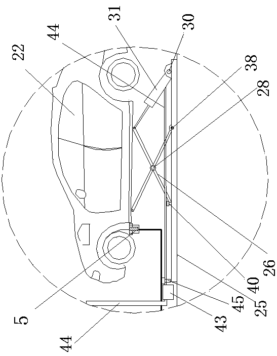
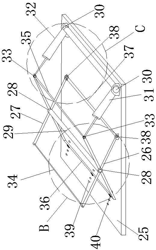
[0057] Example 2. Such as Figure 9-15 As shown, the difference between this embodiment and Embodiment 1 is that the oil storage device includes two recovery oil tanks 2, two new oil tanks 3, and two cleaning oil tanks 11; Six oil inlets 41 and two oil outlets 42 are arranged on the top, each oil inlet 41 and oil outlet 42 of the solenoid valve 4 are provided with electromagnetic valves, each recovery oil tank 2, new oil tank 3, and cleaning oil tank 11 They are respectively connected to an oil inlet 41 of the electromagnetic connecting valve 4 through the oil pipe 12; each oil outlet 42 is connected to a refueling joint 5 through a hose 6; A DC vacuum pump 7 is provided and an electromagnetic reversing valve 8 is provided on the DC vacuum pump 7 . The left sides of the front cross bar 26 and the rear cross bar 27 on the chassis 25 are respectively hinged with a front hydraulic cylinder 31 and a rear hydraulic oil cylinder 32 through a third connecting hinge 30. The central ...

Embodiment 3

[0058] Example 3. Such as Figure 16-20 As shown, the difference between this embodiment and Embodiment 1 is that the oil storage device includes a recovery oil tank 2, two new oil tanks 3, and a cleaning oil tank 11; Four oil inlets 41 and one oil outlet 42 are arranged on the top, each oil inlet 41 and oil outlet 42 of the electromagnetic Unicom valve 4 are provided with electromagnetic valves, and the recovery oil tank 2, the new oil tank 3, and the cleaning oil tank 11 are respectively Connect with an oil inlet 41 of the electromagnetic connecting valve 4 through the oil pipe 12; A DC vacuum pump 7 is provided on the hose 6 and an electromagnetic reversing valve 8 is provided on the DC vacuum pump 7 . The left end bottom of the front cross bar 26, the rear cross bar 27 and the chassis 25 are respectively hinged by a second connecting hinge 38 and the central axis of the hinge shaft of the second connecting hinge 38 is on the same line as the central axis of the fourth co...


PUM


Abstract

The invention discloses a vehicle-mounted intelligent vehicle oil change, cleaning and maintenance system suitable for reservation service. The system is installed on a vehicle body, and comprises anoil storage device, a lubricant oil adding mechanism, a control device, a portable lifting mechanism and a hydraulic pump station, wherein the oil storage device at least comprises a plurality of recovered oil tanks, a plurality of new oil tanks and a plurality of cleaning oil tanks; and the lubricant oil adding mechanism comprises an electromagnetic connection valve, oil inlet ports as many as the oil tanks of the oil storage device, and a plurality of oil outlet ports are formed in the electromagnetic connection valve, and the recovered oil tanks, the new oil tanks and the cleaning oil tanksare connected with one oil inlet port of the electromagnetic connection valve through an oil pipe separately.

Description

technical field [0001] The invention relates to the field of lubricating oil machinery, in particular to an intelligent vehicle oil change, cleaning and maintenance system suitable for scheduled service. Background technique [0002] All vehicle equipment is inseparable from lubricating oil, and the quality of the oil determines the operating efficiency and service life of the vehicle. The main indicators that cause oil quality deterioration are particulate impurities and water content in the oil. As the content of pollutants increases, the use effect of the oil will be greatly reduced and even the equipment will be damaged. In the prior art, when changing the lubricating oil of the vehicle, the owner needs to spare time to go to the 4S shop or maintenance point. At the maintenance point, it takes a long time for the vehicle to change the oil, and the owner has to wait for a long time. If there is a mobile fast oil change on-board system, it can go to the parking place or ...

Claims


Application Information

Patent Timeline
Patent Type & Authority Patents(China)
IPC IPC(8): B66F7/08B66F7/28F16N33/00F16N37/00B60P3/00
CPCB60P3/00B66F7/08B66F7/28F16N33/00F16N37/00
Inventor 刘依诺
Owner 奥吉星(山东)润滑油有限公司
Why Eureka
Try Eureka