Mechanical section hoop positioner and application method thereof

A technology of mechanical joints and locators, which is applied in the directions of earth-moving drilling, drilling pipes, casings, etc., can solve the problems that the induction block cannot be compressed back into the casing 1, and the accident of sticking, and achieves a small amount of wear, Reliable work, increase the effect of induction force

Pending Publication Date: 2018-02-23
BC P INC CHINA NAT PETROLEUM CORP +1
View PDF3 Cites 4 Cited by
  • Summary
  • Abstract
  • Description
  • Claims
  • Application Information

AI Technical Summary

Problems solved by technology

[0003] The purpose of the present invention is to overcome the self-locking phenomenon existing in the existing mechanical joint positioner, resulting in the inductive block can not be compressed back into the housing 1 and even cause a drill stuck accident

Method used


Image

  • Mechanical section hoop positioner and application method thereof
  • Mechanical section hoop positioner and application method thereof
  • Mechanical section hoop positioner and application method thereof

Examples


Embodiment 1

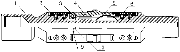
[0023] This embodiment provides a figure 1 The shown mechanical segment hoop positioner includes a housing 1, and a plurality of pressure plates 2 are fixed on the outer wall of the housing 1 at uniform intervals along the circumference, and each pressure plate 2 is provided with a long strip hole, and the long strip hole is embedded with a sensor block 4, an arc-shaped spring piece 5 is placed between the induction block 4 and the housing 1, the arc top of the arc-shaped spring sheet 5 is in contact with the induction block 4, and the contact point of the arc top is close to the bottom of the induction block 4, and the induction block 4 A hinge control mechanism is connected with the block 4 and the pressing plate 2 .

[0024] The design of the mechanical section hoop positioner is as follows: a plurality of pressure plates 2 are evenly distributed in the circumferential direction and attached to the shell 1. After the lamination, the outer diameter remains unchanged. The in...

Embodiment 2

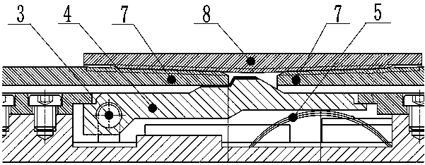
[0028] On the basis of Example 1, such as figure 1 , figure 2 with image 3 As shown, the hinge control mechanism is composed of a small hole 9, a pin shaft 3 and a groove 10, the small hole 9 is set on the induction block 4 along the short side of the elongated hole and runs through the induction block 4, the groove 10 There are two opposite ones on each pressing plate 2, and the two grooves 10 respectively correspond to the two ports of the small hole 9, the pin shaft 3 passes through the small hole 9, and the two ends of the pin shaft 3 overlap the groove 10 inside and can move along the radial direction of the housing 1.

[0029] The upper end of the induction block 4 is horizontally processed with a small hole 9, and the pressure plate 2 is processed with a groove 10 corresponding to the small hole 9 of the induction block 4. The width of the groove 10 is slightly smaller than the diameter of the small hole 9 on the induction block 4. The induction block 4 and the pres...

Embodiment 3

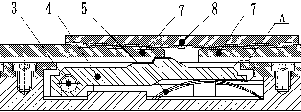
[0032] On the basis of Embodiment 2, the pin shaft 3 is a stepped shaft with a small diameter at both ends and a large middle diameter, and the width of the groove 10 is smaller than the diameter of the small hole 9 . Bearing pin 3 is processed into two ends small middle big step shaft, and its middle shaft just passes through the aperture 9 on the induction block, and the small shaft at two ends just puts in the groove 10 on the pressure plate. Bearing pin 3 is processed with a shoulder, thick in the middle and thin at both ends, so that pin shaft 3 can not come off from the pressing plate like this.


PUM


Abstract

The invention provides a mechanical section hoop positioner and an application method thereof. The positioner comprises a shell, wherein a plurality of pressing plates are uniformly fixed on the outerwall of the shell at intervals along the circumferential direction, a long-strip-shaped hole is formed in each pressing plate, a sensing block is embedded inside the long-strip-shaped hole, an arc leaf spring is cushioned between the sensing block and the shell, the arc roof of the arc leaf spring is in contact with the sensing block, and the sensing blocks and the pressing plates are connected with a hinge control mechanism. The hinge control mechanism consists of small holes, a pin shaft and grooves, the small holes are formed in the sensing blocks along the short edges of the long-strip-shaped holes and penetrate through the sensing blocks, two opposite grooves are formed in each pressing plate, and respectively correspond to two openings of the small holes, the pin shaft passes through the small holes, and the two ends of the pin shaft are in lap joint with the inside of the grooves and can move in the radial direction along the shell. The upper and lower end surfaces of the sensing block are not in contact with the pressing plates all the time, so that the risk of drilling jamming caused by easy self locking of the sensing blocks as the lower end surfaces or the upper end surfaces of the sensing blocks prop against the pressing plates simultaneously when a sensing convex part props against the end surface of a sleeve can be avoided.

Description

technical field [0001] The invention belongs to the technical field of reservoir transformation in oil and gas fields, in particular to a mechanical joint locator and an application method thereof, and is one of the important downhole operation tools in oil and gas field fracturing and acidizing construction operations. Background technique [0002] The mechanical joint locator is one of the important tools commonly used in coiled tubing construction operations. The three-wing positioner currently used in the field relies on the induction protrusion of the induction block to hang on the end face of the casing when passing through the joint collar to generate a large frictional resistance to form a tension pulse in the pipe string, count and locate through the tension pulse String depth position. The sensor block of the locator is limited by the pressure plate to move between the shell 1 and the pressure plate. When the locator passes through the joint hoop, its induction pr...

Claims


Application Information

Patent Timeline
Patent Type & Authority Applications(China)
IPC IPC(8): E21B17/08E21B17/04E21B47/04
CPCE21B17/04E21B17/08E21B47/04
Inventor 李星星隆世明赵宏明张清龙马新东米虎宁张兴荣闫宝泉韩硕冯江宁远
Owner BC P INC CHINA NAT PETROLEUM CORP
Why Eureka
Try Eureka