
Elastic support foil hydrodynamic gas bearing with inherent structure pre-wedge space

A dynamic pressure gas bearing and elastic support technology, which is applied in the direction of air cushion bearings, sliding contact bearings, bearings, etc., can solve the problem of reduced bearing stability and reliability, unfavorable dynamic pressure gas film establishment and stability, and reduced service life of shafts and bearings, etc. problems, to achieve the effect of promoting stable operation, improving operation stability and reliability, and suppressing whirl of the shaft

Pending Publication Date: 2018-02-23
XI AN JIAOTONG UNIV +1
View PDF0 Cites 17 Cited by
  • Summary
  • Abstract
  • Description
  • Claims
  • Application Information

AI Technical Summary

Problems solved by technology

[0004] For foil dynamic pressure gas bearings, during the start-up phase of the rotating shaft, since the effective dynamic pressure film has not been established in the bearing gap, contact friction and wear will inevitably occur on the surface of the rotating shaft and the flat foil surface on the top layer of the bearing, thereby reducing the friction between the rotating shaft and the bearing. service life
At the same time, the worn surface of the shaft and the flat foil surface on the top layer of the bearing are not conducive to the establishment and stability of the dynamic pressure air film, resulting in an increase in the floating time of the shaft and a decrease in the stability and reliability of the bearing.

Method used


Image

  • Elastic support foil hydrodynamic gas bearing with inherent structure pre-wedge space
  • Elastic support foil hydrodynamic gas bearing with inherent structure pre-wedge space

Examples


Embodiment Construction

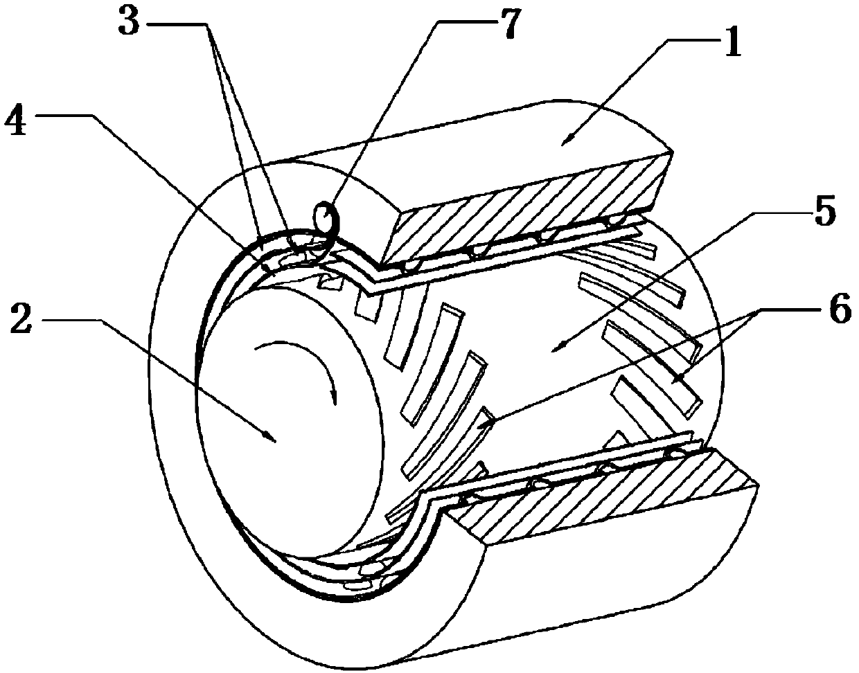
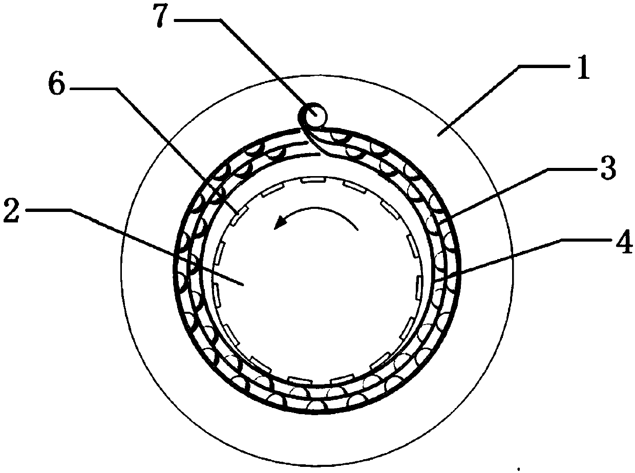
[0024] Example: refer to figure 1 with 2 As shown, an elastically supported foil dynamic pressure gas bearing with an inherent structural pre-wedge space includes a bearing 1 and a rotating shaft 2 inside the bearing 1; an elastic supporting element 3 is arranged inside the bearing 1, and an elastic supporting element 3 The top layer of flat foil 4 is arranged between the shaft 2, the smooth shaft section 5 is arranged in the axial middle area of ​​the surface of the shaft 2, and a row of inclined grooves 6 is respectively arranged on the surface of the shaft 2 and on both sides of the smooth shaft section 5, and the top layer is flat. The inner side of the foil 4 wraps around the rotating shaft 2 and forms a pre-gap between the top flat foil 4 and the rotating shaft 2, while the elastic support element 3 and one end of the top flat foil 4 are fixed on the same position of the bearing 1 and the other end is free.

[0025] The outer end of the inclined groove 6 of the present ...


PUM


Abstract

The invention discloses an elastic support foil hydrodynamic gas bearing with inherent structure pre-wedge space. The elastic support foil hydrodynamic gas bearing comprises a bearing body and a rotary shaft located in the bearing body. An elastic support element is arranged on the inner side of the bearing body. Top-layer flat foil is arranged between the elastic support element and the rotary shaft. A smooth shaft segment is arranged on the axial middle area of the surface of the rotary shaft. The positions, located on the two sides of the smooth shaft segment, of the surface of the rotary shaft are each provided with a line of inclined grooves. The inner side of the top-layer flat foil surrounds and wraps the rotary shaft, a pre-clearance is formed between the top-layer flat foil and the rotary shaft, meanwhile, the elastic support element and one end of the top-layer flat foil are fixed to the same position of the bearing body, and the other end of the top-layer flat foil is free.The elastic support foil hydrodynamic gas bearing has the beneficial effects that a hydrodynamic gas film can be formed at the relatively-low rotating speed with small foil deformation, the rotary shaft and the bearing body are in contact uniformly in the start stage and the stop stage, the contact friction time between the rotary shaft and the bearing body is shortened, wear between the rotary shaft and the bearing body is reduced, and the operation stability and reliability of a system are improved.

Description

technical field [0001] The present invention relates to an elastically supported foil hydrodynamic gas bearing with an intrinsic structural pre-wedge space. Background technique [0002] A gas bearing is a non-contact sliding bearing that uses viscous gas as a lubricant. Gas bearings can be divided into static pressure gas bearings and dynamic pressure gas bearings according to the different mechanisms for generating gas film pressure. The static pressure gas bearing uses an external gas source to provide high-pressure gas, which requires an additional gas supply system, which increases the complexity of the overall system. At the same time, the gas supply system compresses and generates high-pressure gas, which reduces the economy of the system and limits the use of the static pressure gas bearing. application range. The dynamic pressure gas bearing uses the gas film pressure generated by the viscous gas in the wedge-shaped gap of the bearing to support the load when the ...

Claims


Application Information

Patent Timeline
Patent Type & Authority Applications(China)
IPC IPC(8): F16C32/06F16C27/02
CPCF16C27/02F16C32/0603
Inventor 侯予薛绒王伟郭雨赖天伟陈双涛
Owner XI AN JIAOTONG UNIV
Learn More