Dryer provided with uniform air distributing system

A technology of air distribution system and dryer, which is applied in the direction of dryer, drying, progressive dryer, etc. It can solve the problems of uneven drying of local materials, reduction of finished product quantity, and influence on work efficiency, so as to avoid secondary Drying operation, increase the settlement distance, improve the effect of work efficiency

Inactive Publication Date: 2018-02-23
JIANGSU KAIYI INTELLIGENT SCI & TECH
View PDF5 Cites 2 Cited by
  • Summary
  • Abstract
  • Description
  • Claims
  • Application Information

AI Technical Summary

Problems solved by technology

However, due to the large space in the drying box, the hot air introduced by the induced draft fan is often not evenly distributed to every corner of the drying box, which causes the materials in the area near the air outlet to be fully or even excessively Drying, but the insufficient drying of materials in the area far from the air outlet makes local materials dry unevenly, requiring secondary operations, which affects work efficiency
At the same time, the structure in which t...

Method used


Image

  • Dryer provided with uniform air distributing system
  • Dryer provided with uniform air distributing system
  • Dryer provided with uniform air distributing system

Examples


Embodiment 1

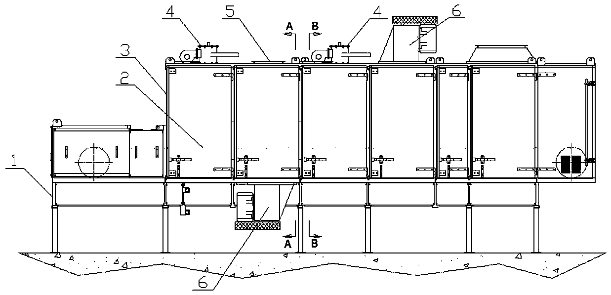
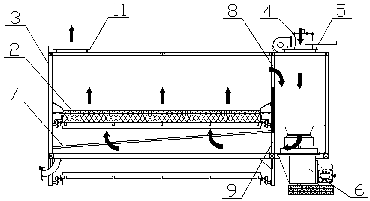
[0020] Such as figure 1 and figure 2 As shown, the dryer with a uniform air distribution system of the present invention includes a frame 1, on which a drying box 3 is arranged longitudinally and continuously, and on the frame 1 is a conveyor belt 2 that runs through the inner cavity of the drying box 3 . One side of the drying box 3 is connected with a hot air device, and there is an air outlet 9 and an air return port 8 between the hot air device and the drying box 3, and the air outlet 9 and the air return port 8 are respectively located on the upper and lower sides of the conveyor belt 2. Described hot blast device comprises hot blast box 10, and burner 4 and induced draft fan 6 are arranged on hot blast box 10, and the heating opening of burner 4 stretches in hot blast box 10, and the induced draft outlet of induced draft fan 6 is aimed at described air outlet 9 . There is an air distribution plate 7 inside the drying box 3 between the air outlet 9 and the conveyor be...

Embodiment 2

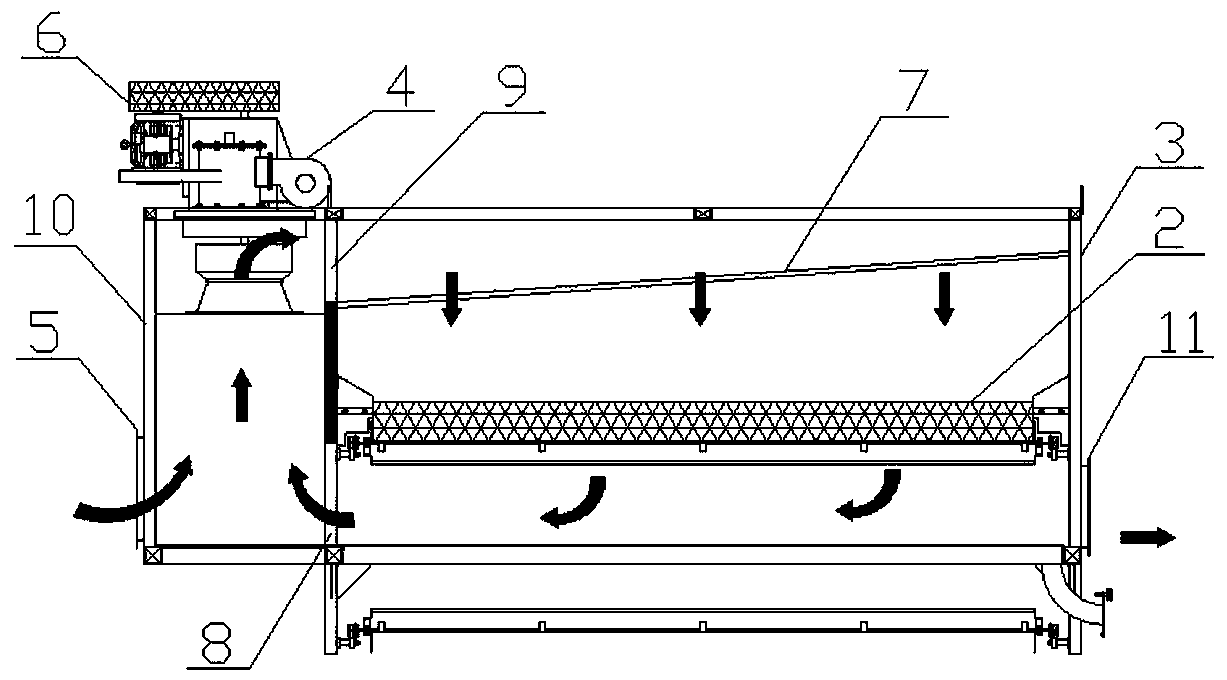
[0023] Such as figure 1 and image 3 As shown, the dryer with a uniform air distribution system of the present invention includes a frame 1, on which a drying box 3 is arranged longitudinally and continuously, and on the frame 1 is a conveyor belt 2 that runs through the inner cavity of the drying box 3 . One side of the drying box 3 is connected with a hot air device, and there is an air outlet 9 and an air return port 8 between the hot air device and the drying box 3, and the air outlet 9 and the air return port 8 are respectively located on the upper and lower sides of the conveyor belt 2. Described hot blast device comprises hot blast box 10, and burner 4 and induced draft fan 6 are arranged on hot blast box 10, and the heating opening of burner 4 stretches in hot blast box 10, and the induced draft outlet of induced draft fan 6 is aimed at described air outlet 9 . There is an air distribution plate 7 inside the drying box 3 between the air outlet 9 and the conveyor bel...


PUM


Abstract

The invention relates to a dryer, in particular to a dryer provided with a uniform air distributing system. The dryer comprises a rack, wherein a drying box is continuously arranged on the rack in thelongitudinal direction, and a conveying belt penetrating through the inner cavity of the drying box is arranged on the rack. A hot air device is connected to one side of the drying box, and an air outlet and an air return port are formed between the hot air device and the drying box and are located on the upper side and the lower side of the conveying belt. The dryer is characterized in that an air distributing plate is arranged in the drying box portion between the air outlet and the conveying belt and is uniformly provided with through holes. The distance between the air distributing plateand the conveying belt is gradually increased from one side to the other side of the air outlet, so that the air distributing plate is obliquely arranged, and the periphery of the air distributing plate is in sealed connection with the inner wall of the drying box. The dryer can conduct uniform air distribution on hot air introduced into the drying box, uniform material drying is achieved, and theoperating efficiency is improved.

Description

technical field [0001] The invention relates to a dryer, in particular to a dryer with a uniform air distribution system. Background technique [0002] As we all know, the dryer is a very common industrial material drying equipment. When it works, the material is located above the bed board in the body and moves along the longitudinal direction of the dryer with the bed board. At this time, the drying device is used to introduce hot air to the material to achieve the purpose of drying the material. [0003] Traditional drying devices for dryers include a burner and an induced draft fan installed outside the drying box and connected in series through pipes. The induced draft fan introduces the hot air heated by the burner into the drying box to dry the material, and then The relatively low temperature cold air in the drying box is guided back to the burner through the return air duct for heating. This cycle realizes the continuous drying operation of the materials in the dr...

Claims


Application Information

Patent Timeline
IPC IPC(8): F26B15/18F26B21/00F26B21/02
CPCF26B15/18F26B21/00F26B21/004F26B21/02
Inventor 江水泉嵇绍卿孙通曹天宇孟娜
Owner JIANGSU KAIYI INTELLIGENT SCI & TECH
Why Eureka
Try Eureka