Plasma pressure sensor and plasma pressure sensing system

A pressure sensor, plasma technology, applied in the direction of measuring fluid pressure, instruments, measuring devices, etc., can solve problems such as data errors, and achieve the effects of long service life, stable glow discharge, and high energy density

Inactive Publication Date: 2018-02-23
INST OF ENGINEERING THERMOPHYSICS - CHINESE ACAD OF SCI
View PDF5 Cites 7 Cited by
  • Summary
  • Abstract
  • Description
  • Claims
  • Application Information

AI Technical Summary

Problems solved by technology

[0009] However, even if the glow discharge is driven by AC, there will still be cathode sputtering on the bare electrode, and the surface state of the electrode and the electrode gap are two crucial factors affecting the characteristics of the sensor, and they are also the main source of error in the experimental data.

Method used


Image

  • Plasma pressure sensor and plasma pressure sensing system
  • Plasma pressure sensor and plasma pressure sensing system
  • Plasma pressure sensor and plasma pressure sensing system

Examples


Embodiment Construction

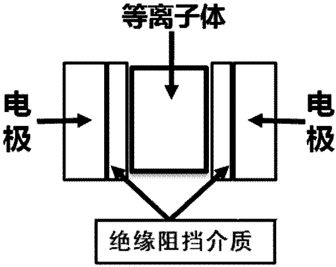
[0039] Based on the technical problem of electrode loss caused by cathode sputtering in the prior art, the present invention provides a plasma pressure sensor and system, including a discharge electrode, the discharge electrode includes two metal electrodes and two The insulating barrier medium on the surface, and the discharge electrode is used to generate plasma between the two insulating barrier mediums driven by an AC power source.

[0040] In order to make the purpose, technical solutions and advantages of the present disclosure clearer, the present disclosure will be further described in detail below in conjunction with specific embodiments and with reference to the accompanying drawings.

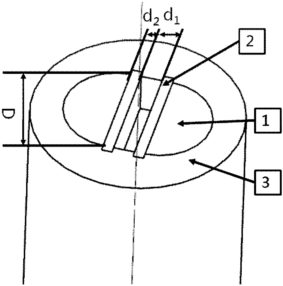
[0041] figure 1 It is a schematic diagram of the structure of the discharge electrode of the embodiment of the present invention, such as figure 1 As shown, the plasma pressure sensor includes a discharge electrode, and the discharge electrode includes two metal electrodes 1 and two ...


PUM

PropertyMeasurementUnit
heightaaaaaaaaaa
thicknessaaaaaaaaaa
diameteraaaaaaaaaa

Abstract

The invention provides a plasma pressure sensor. The plasma pressure sensor comprises a discharge electrode, wherein the discharge electrode comprises two metal electrodes and two insulating block media arranged on the surfaces of the metal electrodes, and plasma is produced between the two insulating block media by the discharge electrode under the driving of an alternating-current power supply.Meanwhile, the invention provides a plasma pressure sensing system. The plasma pressure sensor and the plasma pressure sensing system can reduce cathodic sputtering, are not affected by mass inertia,have potential of breaking through MHZ high-frequency response, can effectively reduce cathodic sputtering of electrode surfaces and prevent electrode loss.

Description

technical field [0001] The invention relates to the fields of high-pressure gas discharge and aerodynamic thermodynamics, in particular to a plasma pressure sensor and a system. Background technique [0002] Experimental measurement technology plays an important role in the study of aerothermodynamics. However, due to the continuous increase of the single-stage pressure ratio of the compressor and the continuous increase of the temperature in front of the turbine, the separation of the reverse pressure gradient and the forward pressure gradient boundary layer of the internal flow of the turbomachinery, and the load on the rotor blade Due to physical phenomena such as radial changes, gap leakage vortex trajectory changes, shock wave position changes, and unsteady interference between moving and stationary blades, the aerodynamic experiment measurement technology is facing many challenges. For example, the high-speed rotation of the rotor blades requires high The limited measu...

Claims


Application Information

Patent Timeline
Patent Type & Authority Applications(China)
IPC IPC(8): G01L23/16G01L27/00
CPCG01L23/16G01L27/005
Inventor 李帆王偲臣杜娟童志庭张宏武
Owner INST OF ENGINEERING THERMOPHYSICS - CHINESE ACAD OF SCI
Why Eureka
Try Eureka