Automatic impedance test device for fingerprint chip

A technology of automatic impedance and testing equipment, applied in the direction of measuring resistance/reactance/impedance, measuring devices, measuring electrical variables, etc., can solve problems such as inconvenient use, achieve simple and convenient operation, avoid human errors, and ensure quality and accuracy.

Inactive Publication Date: 2018-02-23
JIANGSU A KERR BIOLOGICAL RECOGNITION TECH CO LTD
View PDF11 Cites 0 Cited by
  • Summary
  • Abstract
  • Description
  • Claims
  • Application Information

AI Technical Summary

Problems solved by technology

[0003] Metal rings are often used in the fingerprint identification modules of electronic products such as mobile phones and tablet computers. Because their function is to ground to prevent the static electricity of the human body from causing damage to the chip when people touch the fingerprint chip, the DC impedance of the metal ring itself is higher. The smaller the better, however, in the current automated testing, a multimeter is used to test its DC impedance, which is very inconvenient to use

Method used


Image

  • Automatic impedance test device for fingerprint chip
  • Automatic impedance test device for fingerprint chip
  • Automatic impedance test device for fingerprint chip

Examples


Embodiment 1

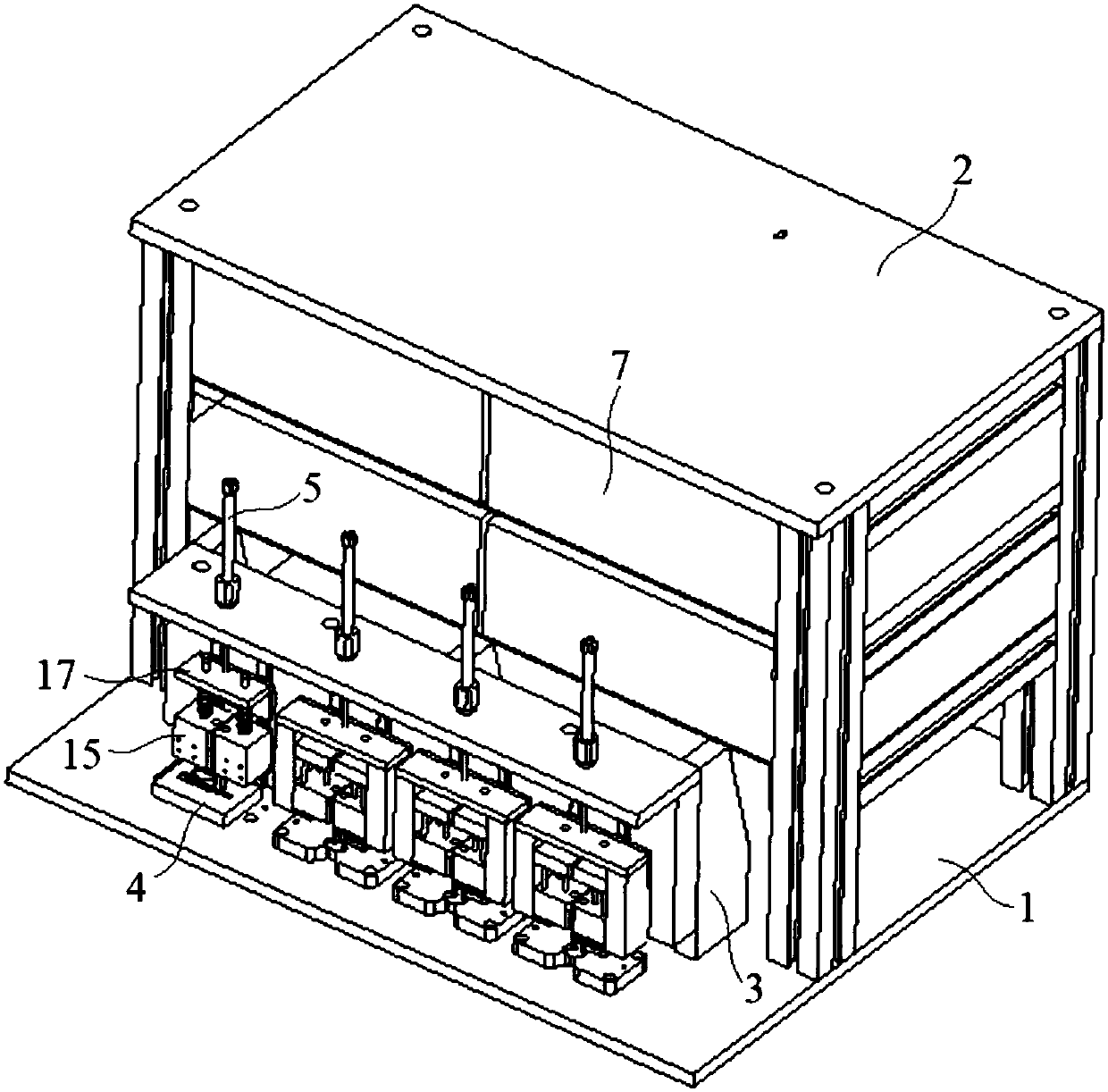
[0025] Embodiment 1: An automatic impedance testing device for a fingerprint chip, comprising a base 1, a support 2, a test frame 3, a test carrier 4, a cylinder 5 and a probe 6, the support 2 is arranged on the upper surface of the base 1 and the support 2 A number of impedance meters 7 are arranged on the top, the test platform 4 is fixedly installed on the upper surface of the base 1 by a number of bolts 8 and located below the probe 6, and the cylinder 5 and the probe 6 are installed on the test frame 3;

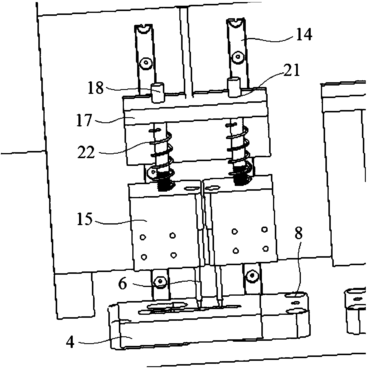
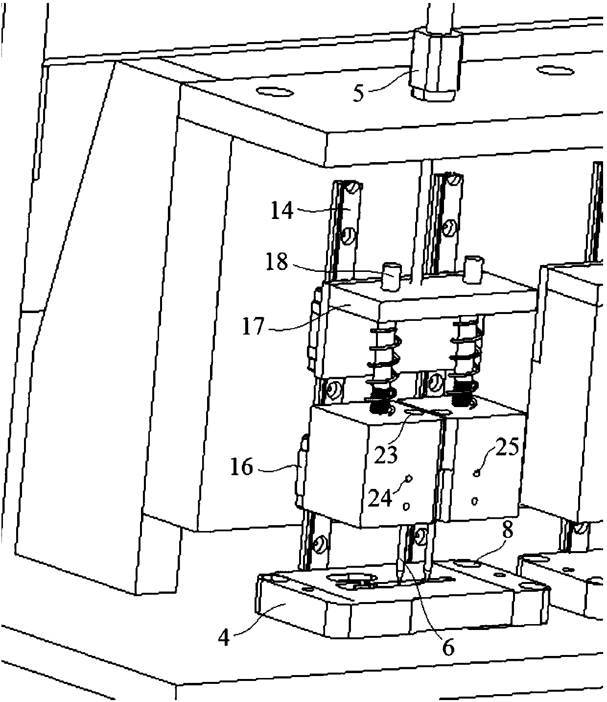
[0026] The front side surface of the test frame 3 is provided with several slide rails 14, and several probe holders 15 are respectively movably connected with the slide rails 14 through sliders 16. The probes 6 are respectively arranged in the several probe holders 15, and the Cylinder 5 is installed on test rack 3 upper surface and the piston rod of cylinder 5 is fixedly connected with a movable plate 17, and this movable plate 17 is slidably arranged on slide rail 14 a...

Embodiment 2

[0030] Embodiment 2: an automatic impedance testing device for a fingerprint chip, comprising a base 1, a support 2, a test frame 3, a test carrier 4, a cylinder 5 and a probe 6, the support 2 is arranged on the upper surface of the base 1 and the support 2 A number of impedance meters 7 are arranged on the top, the test platform 4 is fixedly installed on the upper surface of the base 1 by a number of bolts 8 and located below the probe 6, and the cylinder 5 and the probe 6 are installed on the test frame 3;

[0031] The front side surface of the test frame 3 is provided with several slide rails 14, and several probe holders 15 are respectively movably connected with the slide rails 14 through sliders 16. The probes 6 are respectively arranged in the several probe holders 15, and the Cylinder 5 is installed on test rack 3 upper surface and the piston rod of cylinder 5 is fixedly connected with a movable plate 17, and this movable plate 17 is slidably arranged on slide rail 14 a...


PUM


Abstract

The invention discloses an automatic impedance testing device for a fingerprint chip. The automatic impedance testing device comprises a base, a bracket, a test rack, a test carrier, an air cylinder and a probe. The bracket is disposed on the upper surface of the base and a plurality of impedance meters are disposed on the bracket. The air cylinder is mounted on the upper surface of the test rackand a piston rod of the air cylinder is fixedly connected with a movable plate. A blind hole for inserting the probe is formed in the lower surface of a probe base, a stud hole is communicated with the blind hole, the probe is inserted into the blind hole in the lower surface of the probe base from bottom to top and is fixedly connected with the probe base through a stud embedded in the stud hole.A plurality of threaded holes are formed in the test carrier, the diameter of a nut is greater than the diameter of a first through hole of a T-shaped hole, the diameter of a screw is smaller than the diameter of a second through hole, and the thread of a bolt is matched with the threaded hole of the test carrier. The automatic impedance testing device, as a spring is arranged on a connecting column, not only achieves good detection accuracy, but also protects a chip to be tested from damage, thus the quality and accuracy of the test are ensured.

Description

technical field [0001] The invention relates to a device testing device, in particular to an automatic impedance testing device for a fingerprint chip. Background technique [0002] With the development of science and technology, electronic sensing technology is being applied more and more. Fingerprint identification technology is currently the most mature and cheap biometric identification technology. At present, the fingerprint recognition technology is the most widely used. We can not only see the fingerprint recognition technology in the access control and attendance system, but also have more fingerprint recognition applications in the market: such as laptops, mobile phones, cars, bank payments, etc. Fingerprint recognition technology can be applied. [0003] Metal rings are often used in the fingerprint identification modules of electronic products such as mobile phones and tablet computers. Because they are used as grounding to prevent the static electricity of the ...

Claims


Application Information

Patent Timeline
Patent Type & Authority Applications(China)
IPC IPC(8): G01R27/02
CPCG01R27/02
Inventor 王海昌王凯姜海光陈东位贤龙姚燕杰
Owner JIANGSU A KERR BIOLOGICAL RECOGNITION TECH CO LTD
Why Eureka
Try Eureka