
Novel computer cooling device

A heat dissipation device and computer technology, applied in computing, transportation and packaging, and dispersed particle filtration, etc., can solve the problems of complex computer radiator structure and low heat dissipation efficiency, and achieve improved air cooling efficiency, improved filtration efficiency, and simple design structure Effect

Inactive Publication Date: 2018-02-23
邹城市邹旺食用菌有限公司
View PDF0 Cites 9 Cited by
  • Summary
  • Abstract
  • Description
  • Claims
  • Application Information

AI Technical Summary

Problems solved by technology

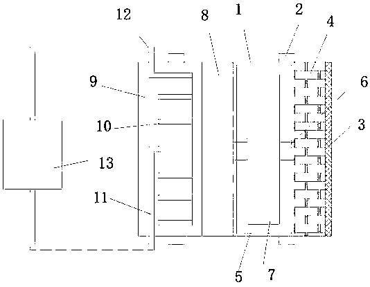
[0005] The technical problem to be solved by the present invention is to overcome the defects of complex structure and low heat dissipation efficiency of existing computer heat sinks, and provide a new type of computer heat dissipation device, which uses a filter layer to fully remove impurities such as dust in the air. Effectively intercept larger debris from entering the filter layer to improve filtration efficiency; the dehumidification device can fully absorb the moisture in the air after dust removal and filtration, preventing condensation water droplets inside the chassis and damaging electronic components; the cooling pipe adopts a spiral structure, greatly improving The air cooling efficiency is improved, and the cooling effect of the computer is improved; the overall design structure is simple and easy to use, changing the idea of ​​traditional components for cooling alone, and reducing the overall ambient temperature in the chassis through cold air to improve the cooling effect and efficiency

Method used


Image

  • Novel computer cooling device
  • Novel computer cooling device
  • Novel computer cooling device

Examples


Embodiment 1

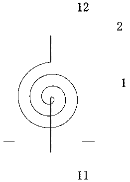
[0020] Such as Figure 1-3 As shown, the present invention provides a novel computer cooling device, comprising a housing 1, mounting bases 2 are arranged on the upper and lower sides of the housing 1, a dust-proof net 3 is installed on the right end of the housing 1, and a dust-proof net 3 is installed on the left side of the housing 1. Filter layer 4, fan bracket 5 is installed on the left side of filter layer 4, fan shaft 6 is arranged in the middle of fan bracket 5, several fan blades 7 are installed in the middle of fan shaft 6, dehumidification device 8 is arranged on the left side of fan bracket 5, dehumidification device 8 The left side is provided with a cooling cabin 9, the middle part of the cooling cabin 9 is provided with a cooling pipeline 10, the middle part of the cooling pipeline 10 is connected with a water inlet pipeline 11, and the upper end of the cooling pipeline 10 is connected with a water outlet pipeline 12, and the water inlet pipeline 11 and the water...


PUM


Abstract

The invention discloses a novel computer cooling device which comprises a shell, wherein mounting seats are arranged on upper and lower sides of the shell; a dustproof net is arranged at the right endof the shell; a filter layer is arranged on the left side of the dustproof net; a fan bracket is arranged on the left side of the filter layer; a fan rotating shaft is arranged in the middle of the fan bracket; a plurality of fan blades are arranged in the middle of the fan rotating shaft; and a dehydrating unit is arranged on the left side of the fan bracket. The device is capable of fully removing dust and other impurities in air. In addition, the dustproof net is capable of effectively preventing sundries of a large size from entering the filter layer, and the filtering efficiency is improved. The dehydrating unit can fully absorb moisture in the air subjected to dust removal and filtration, and the moisture is prevented from being condensed into water drops inside the case so as not to damage electronic components; a cooling pipeline is of a spiral structure, so that the air refrigerating efficiency is greatly improved, and the computer cooling effect is improved; and the novel computer cooling device is simple in overall design and structure and convenient to use, the thought that the traditional components independently dissipate heat is changed, and the cooling effect and cooling efficiency are improved by reducing the overall ambient temperature in the case by cold air.

Description

technical field [0001] The invention relates to a heat dissipation device, in particular to a novel computer heat dissipation device, which belongs to the field of computer heat dissipation. Background technique [0002] High temperature is the enemy of integrated circuits. High temperature will not only lead to unstable operation of the system, shorten the service life, and may even burn some components. The function of the radiator is to absorb the heat and then dissipate it inside or outside the case to ensure that the temperature of the computer components is normal. [0003] Integrated circuits are heavily used in computer components. As we all know, the heat that causes high temperature does not come from outside the computer, but from inside the computer, or inside the integrated circuit. Most heat sinks absorb heat by contacting the surface of the heat-generating components, and then transfer the heat to a distant place through various methods, such as the air in ...

Claims


Application Information

Patent Timeline
IPC IPC(8): G06F1/20G06F1/18B01D46/00B01D46/12B01D53/26
CPCB01D46/003B01D46/12B01D53/26G06F1/183G06F1/20B01D2279/45B01D46/645
Inventor 高萌
Owner 邹城市邹旺食用菌有限公司
Learn More