
Reactive compensation communication method based on intelligent integrated capacitor

A technology integrating capacitors and communication methods, applied in reactive power compensation, reactive power adjustment/elimination/compensation, electrical components, etc. Stability and other issues

Inactive Publication Date: 2018-02-23
ZHEJIANG SHUANGFENG ELECTRIC
View PDF1 Cites 1 Cited by
  • Summary
  • Abstract
  • Description
  • Claims
  • Application Information

AI Technical Summary

Problems solved by technology

The compensation cabinet has a large volume, complex installation and wiring, difficult maintenance, and low reliability of the whole machine. At the same time, one controller controls the switching of all compensation capacitors. When the controller fails, the entire compensation equipment stops
This compensation mode has the potential problem of the bottleneck effect of the controller, and cannot achieve reactive power balance and voltage stability.
[0004] Therefore, the traditional reactive power compensation device can no longer meet the rapidly growing demand of modern large-scale power loads, and the intelligent integrated capacitor reactive power compensation mode can realize intelligent control and solve the problem of low voltage caused by insufficient reactive power in the distribution network
[0005] Traditional capacitor switching uses composite switches and thyristors as switching devices. Although thyristors have many advantages, their ability to withstand overvoltage and overcurrent is poor, and overvoltage and overcurrent in a short period of time will damage them and cannot repair
The operating state of the power grid is complex and unpredictable, so the thyristor, as a switching device, is often damaged

Method used


Image

  • Reactive compensation communication method based on intelligent integrated capacitor
  • Reactive compensation communication method based on intelligent integrated capacitor
  • Reactive compensation communication method based on intelligent integrated capacitor

Examples


Embodiment Construction

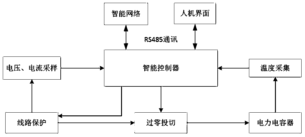
[0011] The invention provides a reactive power compensation communication method based on intelligent integrated capacitors, such as figure 1 As shown, the method includes:

[0012] Step 101, modular design of intelligent integrated capacitors.

[0013] Step 102, adopt high-performance, high-precision TMS320C28x series processor DSP and low-power consumption, high-performance STC89C53 microcontroller to form the intelligent controller of the system.

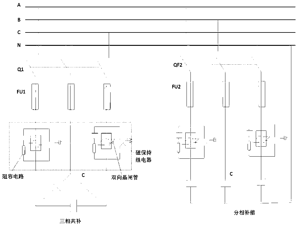
[0014] In step 103, an intelligent integrated capacitor zero-crossing switch is constructed by designing and constructing a high-power magnetic latching relay, a bidirectional thyristor, a resistance-capacitance absorption circuit, and a line protection device.

[0015] Step 104, the circuit adopts power electronic technology and zero-crossing switching technology, and utilizes the fast turn-on of the bidirectional thyristor and the zero voltage drop of the contact of the high-power magnetic latching relay to realize complementa...


PUM


Abstract

The invention aims at providing a modularized intelligent reactive compensator. A reactive compensation mode of intelligent control is achieved through an intelligent integrated capacitor composed ofa power grid parameter sampler, an intelligent network, an intelligent controller, a zero-off switching device, a power capacitor, a circuit protector and other units, and the problem of low voltage caused by insufficient reactive power of a large power distribution network is effectively solved. The modularized intelligent reactive compensator mainly comprises modular design of the intelligent integrated capacitor, study on the intelligent controller as a control core of the intelligent integrated capacitor, the improvement in the zero-off switching device and technical support of intelligentnetwork communication. According to the modularized intelligent reactive compensator, the defect of a traditional compensation device is greatly overcome, and the prominent advantages of zero-off switching, intelligent networks, split-phase compensation, temperature protection, man-machine interfaces, easy wiring, convenient capacity increasing, high reliability, low power consumption and the like are achieved.

Description

technical field [0001] The invention relates to the field of reactive power compensation intelligent capacitor equipment, in particular to devices and methods for communication protocols, intelligent control, zero-crossing switching, and intelligent network communication under heterogeneous networks. Background technique [0002] With the country's strong support for improving the quality of life of residents, people's living conditions continue to improve, and power consumption is also increasing, and low-voltage phenomena are gradually exposed; and the use of a large number of single-phase household appliances will lead to three-phase loads. Balance, the voltage fluctuation of the distribution network is large, and in severe cases, it will damage the electrical equipment. Therefore, people's requirements for voltage quality are getting higher and higher. [0003] Most of the current distribution network still uses traditional reactive power compensation devices, and adopts...

Claims


Application Information

Patent Timeline
IPC IPC(8): H02J3/18H02J13/00
CPCH02J3/1821H02J13/0062Y02E40/30
Inventor 林宗春王建荣
Owner ZHEJIANG SHUANGFENG ELECTRIC
Learn More