Double self-lubricating bearing motor

A technology of self-lubricating bearings and shaft tubes, applied in the direction of electrical components, electromechanical devices, electric components, etc., can solve the problems of failure to form normal oil film, damage to the surface of the mandrel, and aggravated wear, so as to reduce up and down movement and left and right shaking , reduce left and right swing and up and down movement, reduce the effect of heat generation

Pending Publication Date: 2018-02-23
DONGGUAN YOUWEI ELECTRONICS
View PDF5 Cites 0 Cited by
  • Summary
  • Abstract
  • Description
  • Claims
  • Application Information

AI Technical Summary

Problems solved by technology

[0003] Ordinary self-lubricating bearing structure fan motor, its life is limited by the oil content of self-lubricating bearing lubricating oil, due to the limitation of processing technology and materials, at present, under the premise of maintaining the necessary strength, self-lubricating bearings can achieve an oil content of 20% Left and right, subject to this limitation, and the design of the fan motor, the self-lubricating bearing and the rotating shaft are not sealed, so there are problems of loss and volatilization of lubricating oil, vibration or angle changes during the rotation of the fan motor rotor, or occasional lubrication during motion If the oil is not replenished between the mandrel and the self-lubricating bearing in time, the oil film will be damaged or a normal oil film will not be formed, resulting in direct contact without oil film between the mandrel and the bearing, which will cause bearing wear and mandrel An important reason for surface damage, which will cause the operating lubrication environment between the two to deviate from the normal range of design, produce abnormal noise, and aggravate wear, which is another important reason for the limited life of self-lubricating bearings

Method used


Image

  • Double self-lubricating bearing motor
  • Double self-lubricating bearing motor
  • Double self-lubricating bearing motor

Examples


Embodiment Construction

[0017] The technical solution of this patent will be further described in detail below in conjunction with specific embodiments.

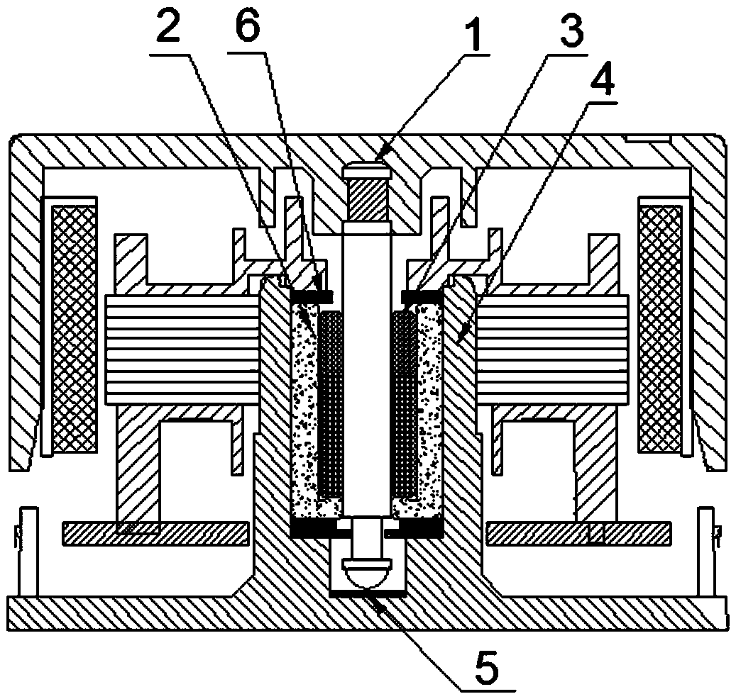
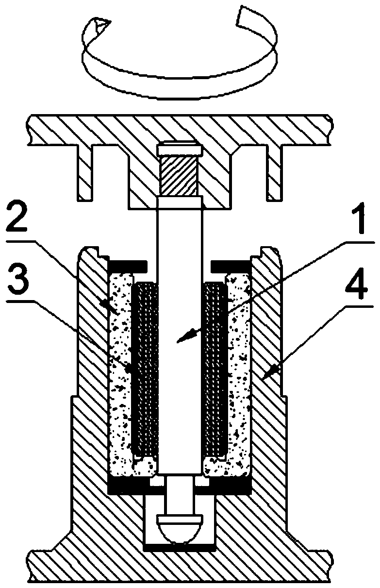
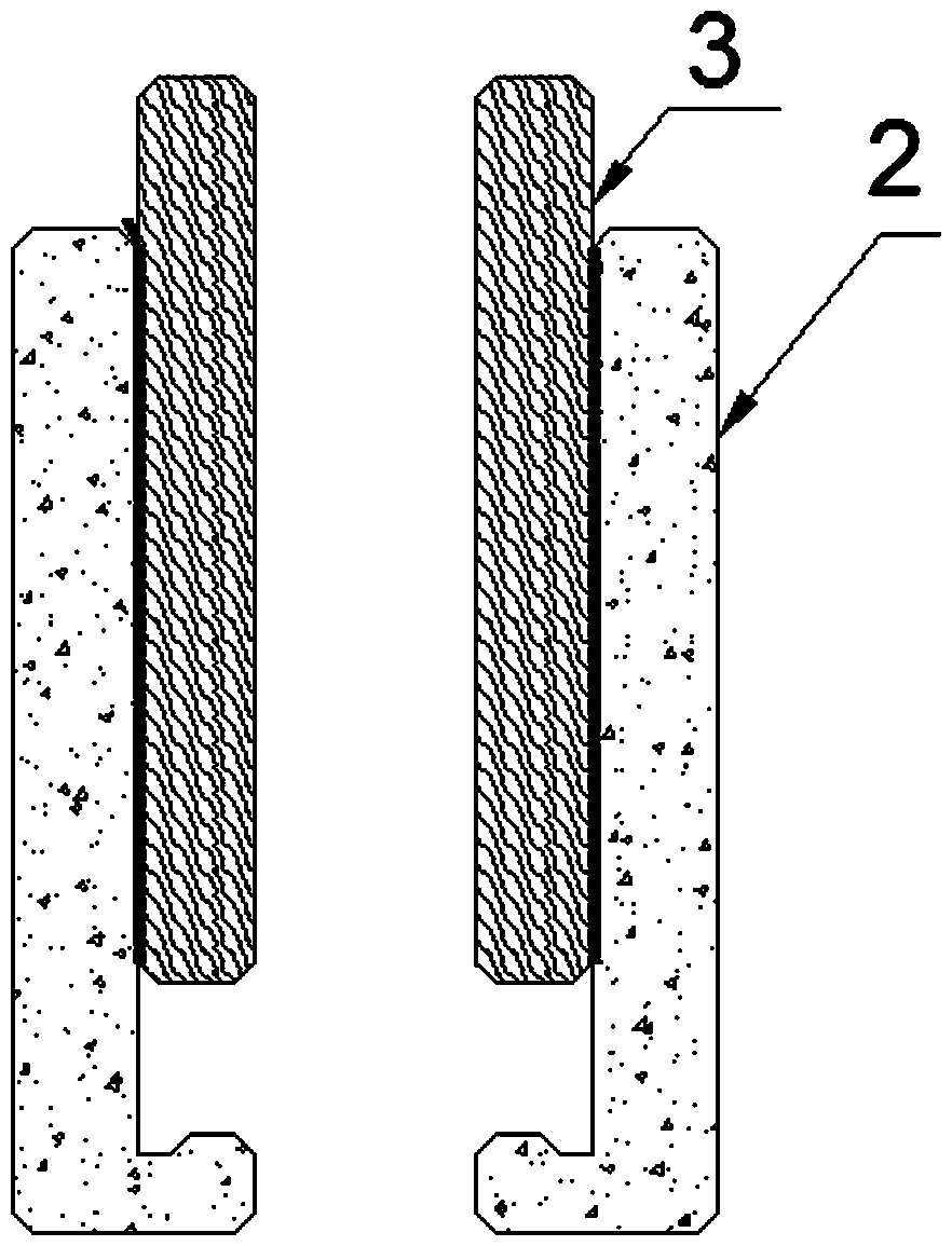
[0018] see Figure 1-4 , a double self-lubricating bearing motor, including a stator and a rotor, a shaft tube 4 is sleeved inside the stator, a mandrel is provided on the rotor, and a first self-lubricating bearing 2 and a second self-lubricating bearing 2 are inserted inside the shaft tube 4 Self-lubricating bearing 3, the first self-lubricating bearing 2 and the shaft tube 4 are in a tight fit. After assembly, the first self-lubricating bearing 2 is fixed in the shaft tube 4 and cannot move freely relative to each other. The second self-lubricating bearing 3 is slid into the first self-lubricating bearing In the inner hole of the first self-lubricating bearing 2, the inner hole of the second self-lubricating bearing 3 is provided with a mandrel 1, and the mandrel 1 is inserted through the inner hole of the second self-lubricating bearing 3, and ...


PUM


Abstract

The invention discloses a double self-lubricating bearing motor. The motor comprises a stator and a rotor, and the motor is characterized in that a shaft tube sleeves the interior of the stator, a mandrel is arranged on the rotor, a first self-lubricating bearing and a second self-lubricating bearing are inserted into the interior of the shaft tube, the first self-lubricating bearing is inserted into the shaft tube, the second self-lubricating bearing is slidably inserted into an inner hole of the first self-lubricating bearing, and the mandrel is arranged in an inner hole of the second self-lubricating bearing. According to the double self-lubricating bearing motor, the relative rotation motion of the mandrel and the single self-lubricating bearing is decomposed into a superposition of the normal rotation motion of the mandrel relative to the self-lubricating bearings and the slow and intermittent rotation motion of the one self-lubricating bearing relative to the other self-lubricating bearing. In the case of vibration or changes in the angle of the rotor, the relative rotation motion of the mandrel and the second self-lubricating bearing is transferred between the second self-lubricating bearing and the first self-lubricating bearing, thereby greatly reducing the wear caused by the direct relative rotation motion of the mandrel and the self-lubricating bearings, reducing theheat and greatly increasing the service life of the motor.

Description

technical field [0001] The invention relates to the field of motors, in particular to a double self-lubricating bearing motor. Background technique [0002] The lubricating fluid is the lubricating medium when the mandrel corresponds to the bearing rotation, so as to reduce the friction loss between them. The lubricating oil will be gradually destroyed and lost with the friction of the rotation, and this loss will increase geometrically with the increase of temperature . Therefore, reducing the relative friction and reducing the temperature rise of the rotation can significantly improve the life of the self-lubricating bearing motor. [0003] Ordinary self-lubricating bearing structure fan motor, its life is limited by the oil content of self-lubricating bearing lubricating oil, due to the limitation of processing technology and materials, at present, under the premise of maintaining the necessary strength, self-lubricating bearings can achieve an oil content of 20% Left a...

Claims


Application Information

Patent Timeline
Patent Type & Authority Applications(China)
IPC IPC(8): H02K5/16H02K5/24
CPCH02K5/16H02K5/24
Inventor 覃小荣覃刘柱
Owner DONGGUAN YOUWEI ELECTRONICS
Why Eureka
Try Eureka