Novel constant temperature controllable film plating machine

A coating machine, constant temperature technology, applied in sputtering coating, ion implantation coating, vacuum evaporation coating and other directions, can solve the problems of cumbersome manufacturing process, short service life, high cost, and achieve simple design and structure realization, reduce Production difficulty and cost, effects that are easy to produce and use

Active Publication Date: 2018-02-27
NORTH CHINA UNIVERSITY OF TECHNOLOGY
View PDF4 Cites 3 Cited by
  • Summary
  • Abstract
  • Description
  • Claims
  • Application Information

AI Technical Summary

Problems solved by technology

However, this patented product has the following problems: (1) the cooling water passage adopts the form of a shell, and the shell must be sealed and connected with the outer wall of the cavity. Both the outer wall of the body and the shell need to be equipped with corresponding fastening structures, which are complicated to manufacture and costly, and when the water pressure in the shell is too high, the shell will be separated from the outer wall of the cavity and lose the cooling function; Welding and other forms require a lot of man-hours and have a short service life; (2) only cooling can be achieved, but the working temperature in the coating machine cavity cannot be precisely controlled, and the constant working temperature cannot be effectively guaranteed; (3) It can be seen from the attached drawings that the main body structure of the coating machine is relatively complicated, the production process is relatively cumbersome, and it is inconvenient to use

Method used


Image

  • Novel constant temperature controllable film plating machine
  • Novel constant temperature controllable film plating machine
  • Novel constant temperature controllable film plating machine

Examples


Embodiment Construction

[0022] Preferred embodiments of the present invention will be described in detail below in conjunction with the accompanying drawings.

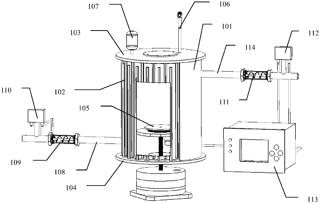
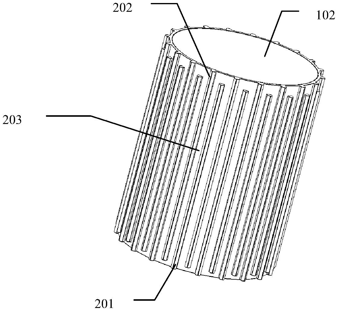
[0023] refer to Figure 1 to Figure 5 , the preferred embodiment of the present invention provides a new type of constant temperature controllable coating machine, comprising a vacuum furnace chamber and a workpiece table 105 inside thereof, the vacuum furnace chamber is composed of a furnace top 103, a furnace bottom 104, an inner cylinder 102 and an outer cylinder 101, the inner cylinder 102 is set inside the outer cylinder 101 and there is an interlayer space between the outer surface of the inner cylinder 102 and the inner surface of the outer cylinder 101, the top of the inner cylinder 102 and the outer cylinder 101 Sealed connection with the bottom surface of the furnace roof 103, and sealed connection between the bottom end and the top surface of the furnace bottom 104;

[0024] The interlayer space is provided with a plurality of alt...


PUM


Abstract

The invention provides a novel constant temperature controllable film plating machine. The novel constant temperature controllable film plating machine comprises a vacuum furnace chamber and a workpiece table arranged in the vacuum furnace chamber. The vacuum furnace chamber is formed by combing a furnace top, a furnace bottom, an inner barrel with an outer barrel. An interlayer space is reservedbetween the inner barrel and the outer barrel. The layered space is internally provided with a plurality of alternately-arranged first vertical protrusion strips and second vertical protrusion stripsso that a circulation channel can be formed. A water inlet pipeline and a water outlet pipeline on the outer barrel are provided with flow control valves correspondingly. A thermocouple is fixed to the furnace top. The flow control valves and the thermocouple are connected with a controller. Structures of existing film plating machines capable of conducting cooling are optimized and improved, thenovel constant temperature controllable film plating machine is simple in structure, easy to manufacture and low in cost, by controlling flow of cooling water, the operation temperature of a vacuum chamber is controlled, the vacuum chamber of the film plating machine can continuously work in the certain constant temperature state, and the operation stability is good.

Description

technical field [0001] The invention relates to the technical field of vacuum coating machines, in particular to a novel constant temperature controllable coating machine. Background technique [0002] The vacuum chamber is a key structural part of the coating machine. It often bears relatively high temperatures during work, and the temperature is not easy to be controlled and detected. The temperature of the vacuum chamber has a relatively large impact on the coating effect and effective continuous working time of the coating machine. big impact. Generally, in order to improve the cooling effect of the vacuum chamber, the coating machine is often used to stop working for a period of time and then cool down naturally, but this will seriously affect the production cycle and efficiency. [0003] The patent document of publication number CN103290360A discloses a vacuum coating machine cavity cooling device with improved structure, including a vacuum coating machine cavity, and...

Claims


Application Information

Patent Timeline
Patent Type & Authority Applications(China)
IPC IPC(8): C23C14/24
CPCC23C14/24
Inventor 刘东刘瑛王放
Owner NORTH CHINA UNIVERSITY OF TECHNOLOGY
Why Eureka
Try Eureka